Treatment & service / Design study / RECEIVER-ISOLATION-R1
Consider the disconnected state.
Socket, poppet and replaceable cartridge geometry for receiver servicing.
Retained development study. Dimensions, names and checks belong to this revision—not automatically to the retrofit-only product. Manufactured tank shells are deferred. No installation instruction, certification or manufacturing release is represented.
The source reasoning
Why this detail was investigated.
Removal changes the fluid boundary. This study makes the nominal closure sequence visible while leaving physical isolation and retained liquid unresolved.
Read the research and limits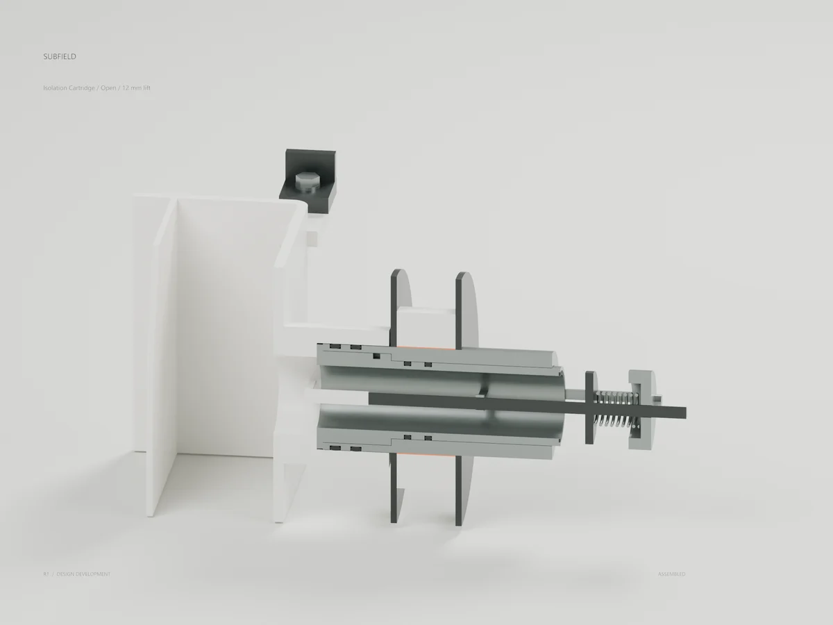
Research record
The detail behind
the study.
Source-linked work for this revision. Reported checks describe the stated model or test; physical qualification and applicability to the current retrofit remain separate.
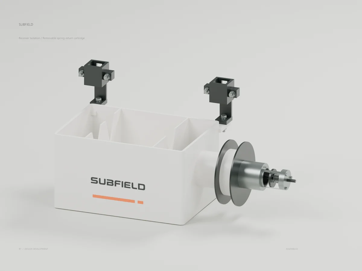
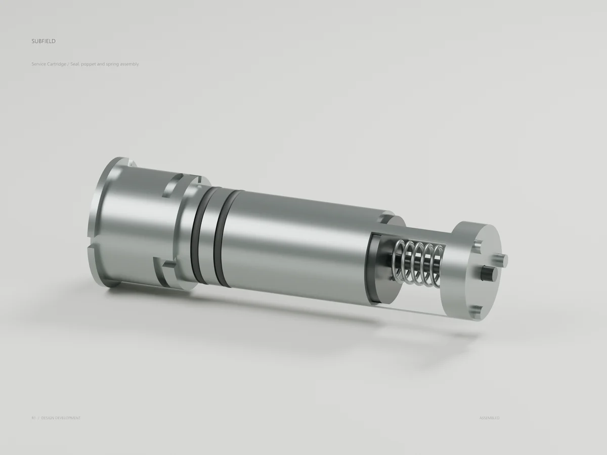
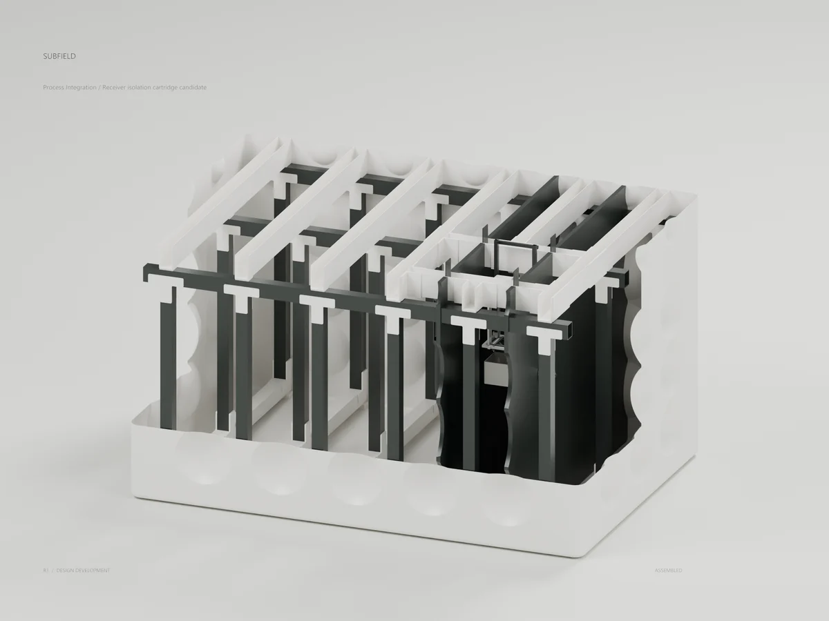
Six CAD-driven views of the removable spring-return cartridge. Development concept; isolation and manufacturing qualification remain open.
Review PDF · Assembly STEP · 3D model
Receiver / revised socket
Open / probe holds 12 mm lift
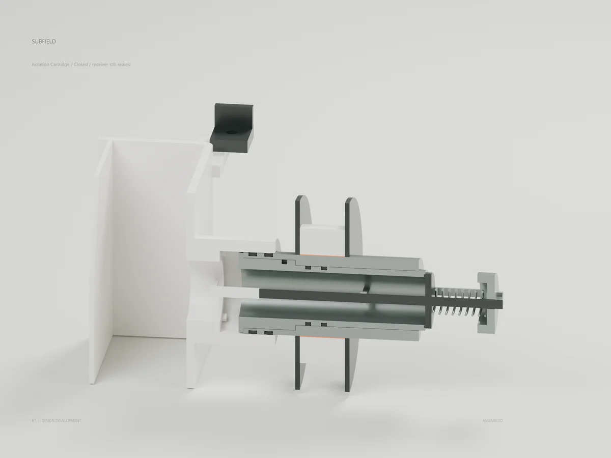
Closed / both socket seals engaged
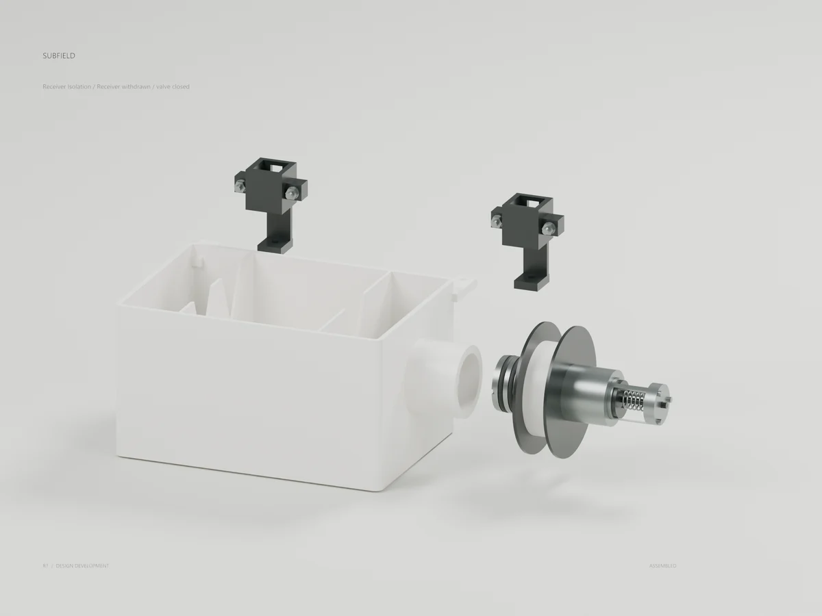
Receiver withdrawn / valve remains
Cartridge / replaceable working parts
Tank integration / shallow case
This is a CONCEPT development package, with original Subfield artwork on actual CAD meshes. Physical isolation, hydraulic performance, materials and manufacturing qualification remain open.
CAD uses mm. GLB/Blender use metres. Receiver-local XY origin is tank [830,-475]; Z is already tank Z. The media origin is [830,-460,1100]. The new receiver return spout ends at X-150, the socket at X186. Its 65 mm negative-X / 10 mm negative-Y release preserves the 30 mm external handling allowance checked against the shallow tank.
The probe holds the poppet 12 mm open. Nominal spring-return closure occurs after 12 mm withdrawal, 1.5 mm before the downstream socket ring first becomes exposed. This is not a qualified tolerance budget, leak-tight closure, non-spill connection or seat verification. Establish the real service and isolation condition before any physical handling. Retained liquid and captured drainage remain unresolved.
The cartridge has a 32 mm throat, 6 mm stem, compressed radial/face seal studies and a preliminary helical spring. Its three-pin bayonet unlocks by 45 degrees, then withdraws 200 mm before lifting. The effective lock-pin inner radius is lock_socket.pin_inner_radius = 20.5 mm; the earlier inherited bayonet field is not used by this variant. Cartridge removal exposes the sleeve and requires separate chamber level/isolation. No live cartridge exchange, grade tool, full guide, lifting attachment or verified no-entry procedure is provided.
Nominal cap screws omit threads. Material/finish colors do not select an alloy, resin or elastomer. The ideal spring/load screen is not structural, fatigue, corrosion or isolation qualification. The open receiver still needs a complete abnormal EQ/backwater and untreated-bypass strategy, actual pumps/media, calibrated split, controlled final flow and protected service drains.
Complete material/process selection, dimensional tolerances, spring and seal manufacture, retention and joint qualification, drawings/tooling/inspection and physical approval before fabrication release. No production release is included.
Source and revision record
Source: receiver-isolation-r1/index.html
Source SHA-256: 796612574b944ed10660c6b6a618685235dbcab04c53cf62d7545ab9f3dde7fb
Geometry and images describe this development revision. Current product ratings and manufacturing release require separate qualification.
Keep exploring the research.
Treatment & service / Development study
Subfield UV · Service review R2
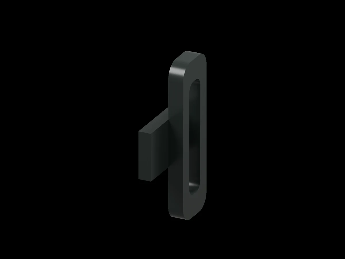
Inspect the separate two-solid handle correction candidate and the engineering limits behind it.
Treatment & service / Design study
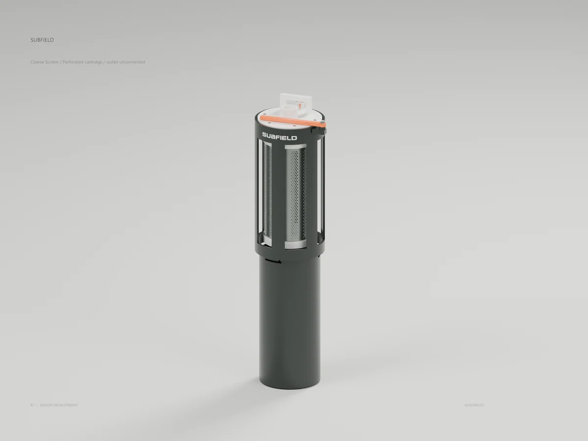
Coarse screen
A perforated cartridge, capture mechanism and contained-removal geometry.
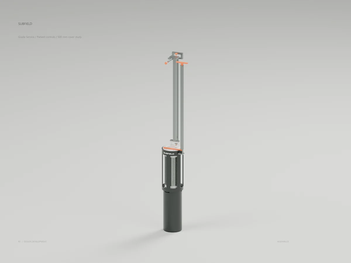
Treatment & service / Design study
Screen grade controls
Long controls, capture hardware and the screen extraction arrangement.
Return to the current product.
Explore the retrofit-only platform and its compatibility, installation and service objectives.
Explore the retrofit