Treatment & service / Design study / SCREEN-GRADE-R1
Service from the surface.
Long controls, capture hardware and the screen extraction arrangement.
Retained development study. Dimensions, names and checks belong to this revision—not automatically to the retrofit-only product. Manufactured tank shells are deferred. No installation instruction, certification or manufacturing release is represented.
The source reasoning
Why this detail was investigated.
The mechanism brings control points toward grade. The extraction height still requires a qualified lifting approach and defined liquid handling.
Read the research and limits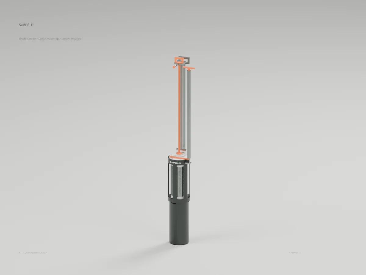
Research record
The detail behind
the study.
Source-linked work for this revision. Reported checks describe the stated model or test; physical qualification and applicability to the current retrofit remain separate.
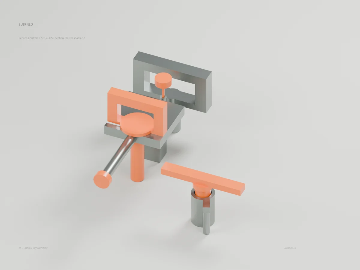
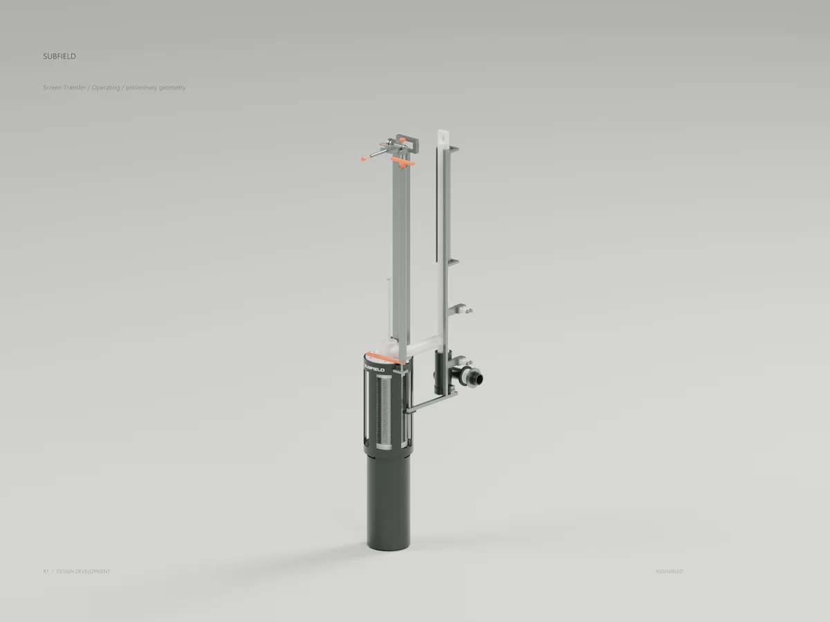
Subfield grade-control concept: a capture mast, guided plunger, independent head retainer and retained service cap. Actual CAD at the 500 mm cover datum.
42 parts; 147 passing CAD tests. Process isolation, a qualified lifting path, materials and manufacturing release remain in development.
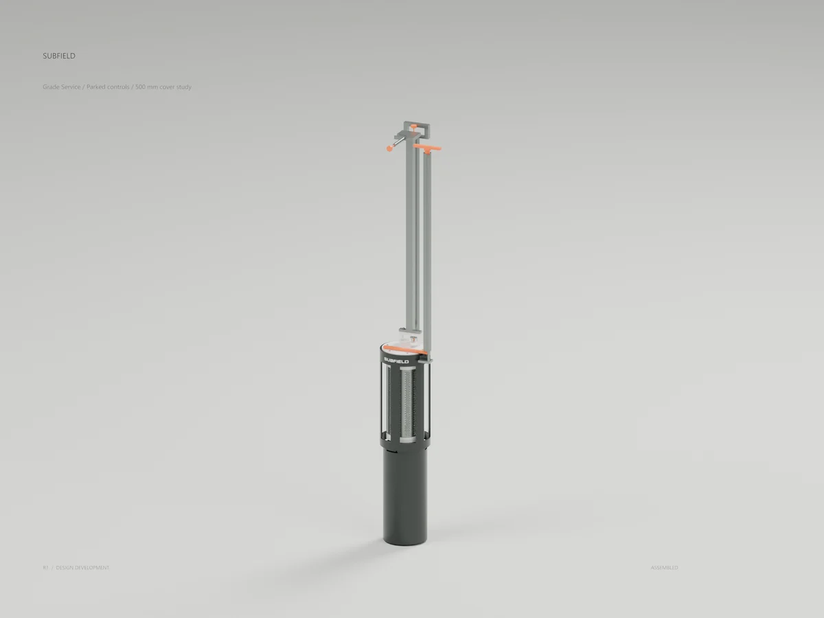
Parked / controls below the guard
Capped / before capture
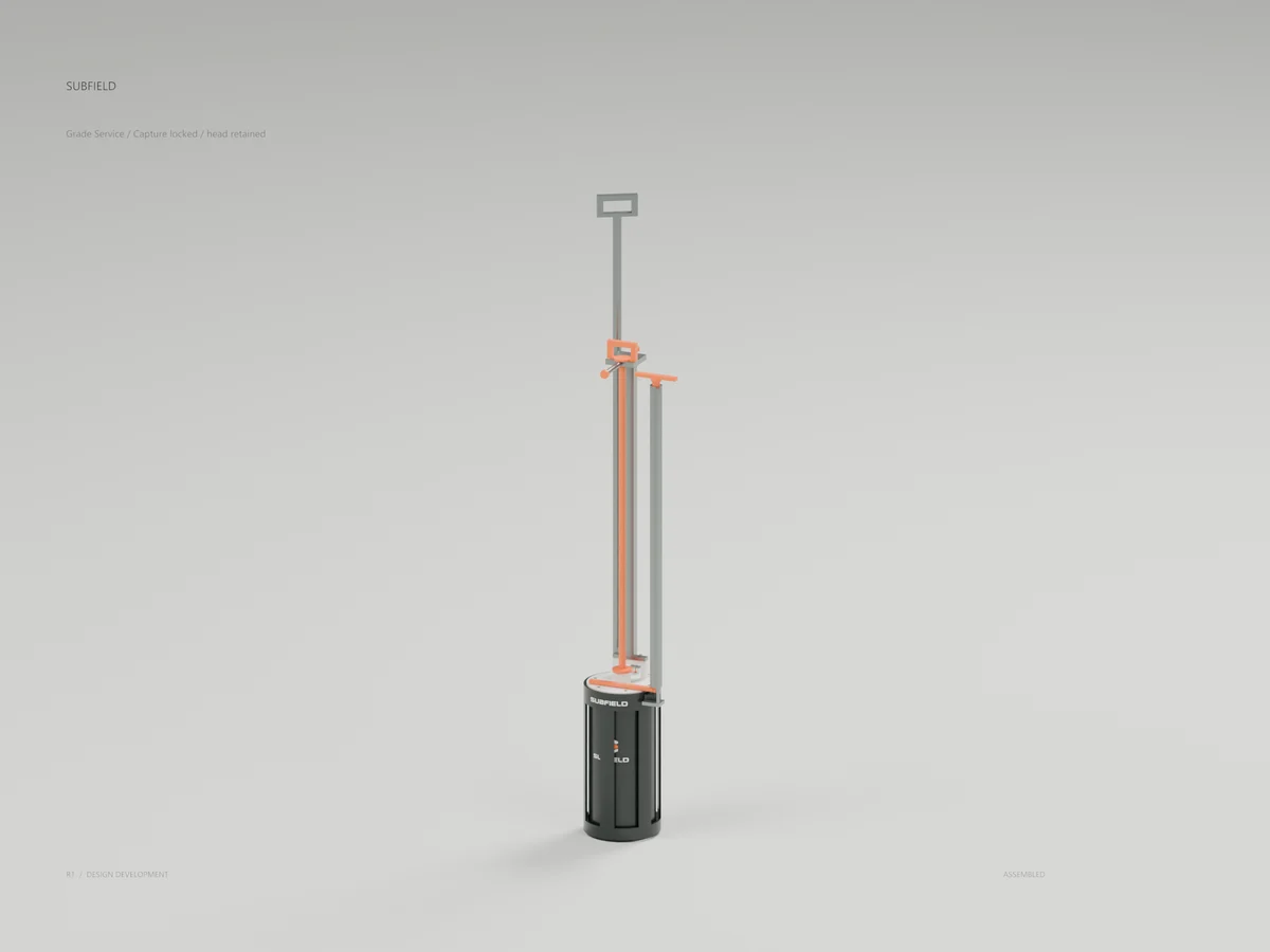
Locked / before head release
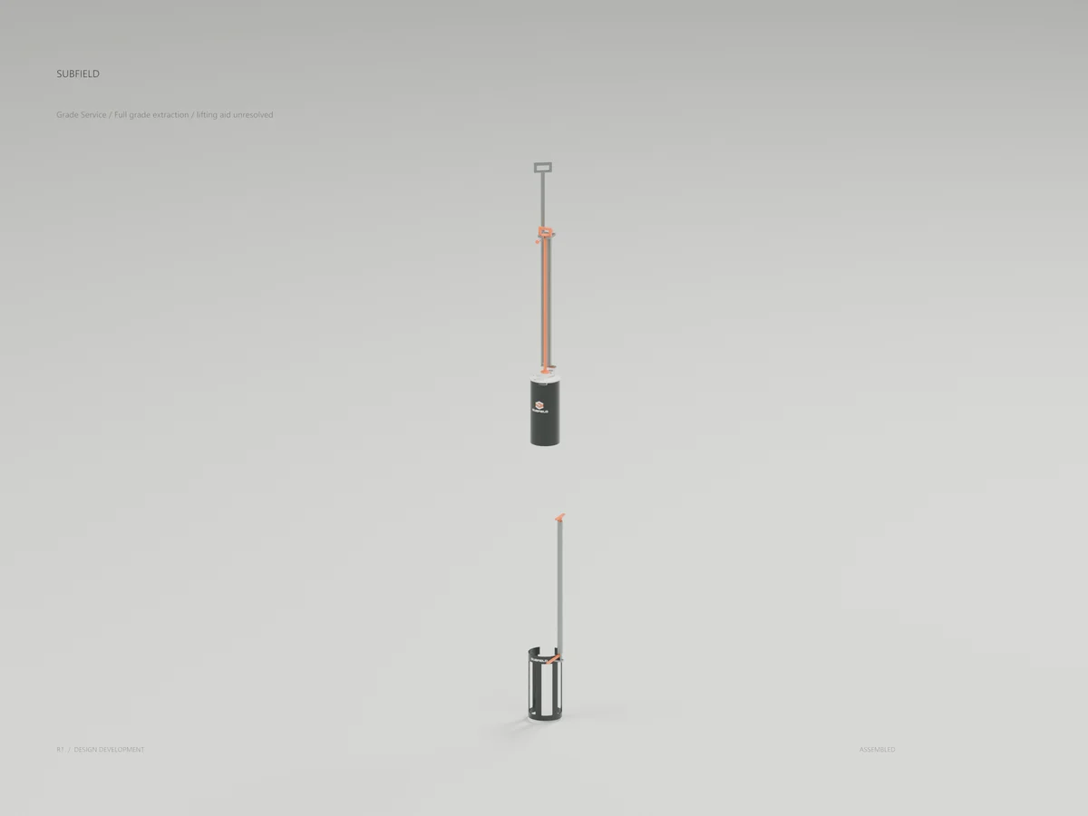
Extracted / lifting aid unresolved
Grade controls / actual CAD section
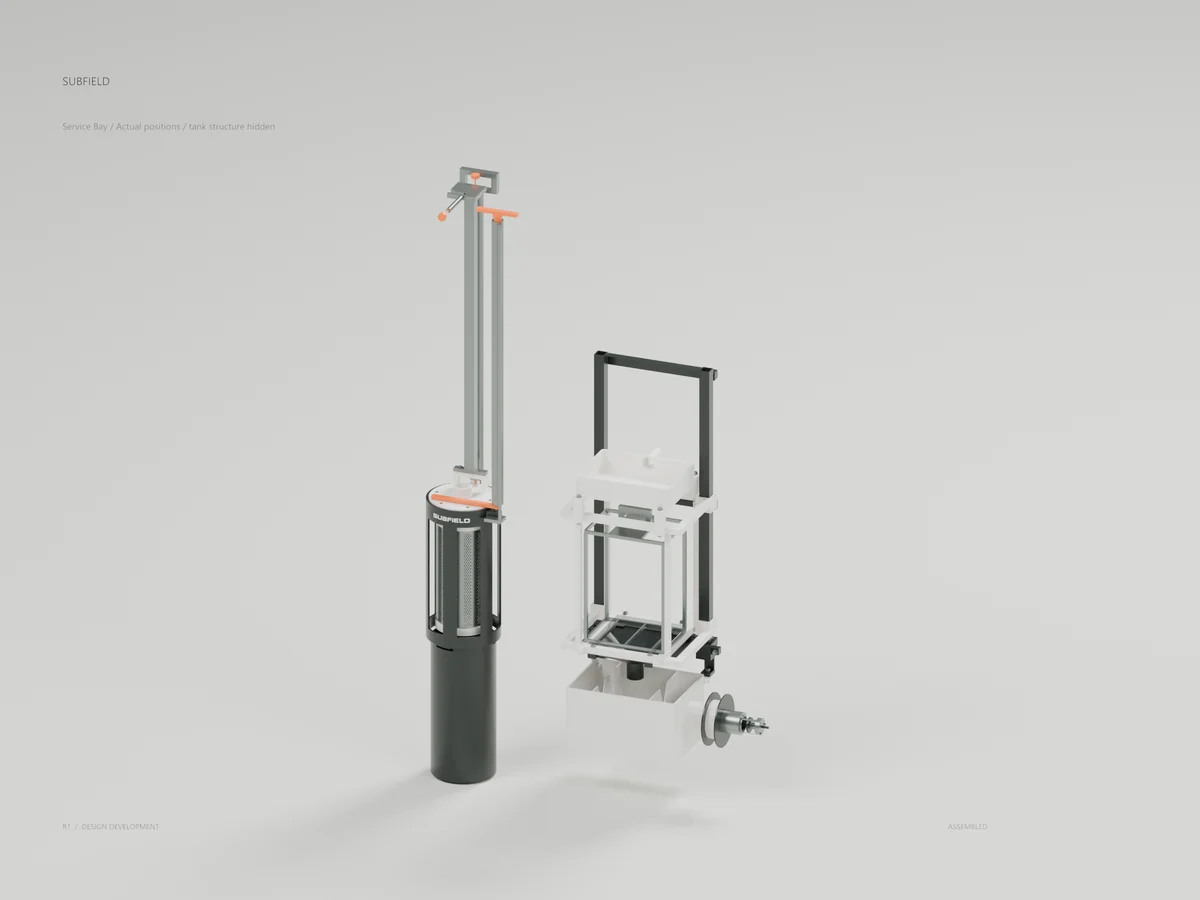
Service bay / tank structure hidden
CAD geometry is authoritative. Artwork and studio finishes are presentation only. See the PDF and design records for assumptions, verification and remaining engineering.
CONCEPT alternative for the existing F1 coarse screen at 500 mm cover. Original Subfield finishes are applied to actual CAD. Process transfer/isolation, housing support, a qualified lifting aid, materials, seals, tolerances and manufacturing release remain open.
STEP uses mm, Z up. Screen-local origin in the tank is [435,-550,1150]. Raw cup and mast are raised and unturned, with the lock plunger down. State assemblies apply the actual placements. GLB/Blender use metres. The seated assembly has 40 parts; service states include the long cap and its separate ring, for 42 parts. The captured assembly raises 340 mm and turns 30 degrees, the plunger travels 9.5 mm, and the head retainer rotates 90 degrees. Full extraction is 1467 mm. Its highest grip finishes 1712 mm above grade, so the geometry does not establish manual lifting capability.
The cap keeper withdraws 35 mm. The cap then raises 30 mm, moves 60 mm left through the side-loading guide, and withdraws. This is a tested geometric path, not a released physical procedure. Correct isolation, liquid containment, required operating pauses and waste handling must be established independently. The keeper is captive but has no positive closed-position detent. The controls do not mechanically prevent every wrong or missing-part state.
The capture mast, long controls, closed ends and support frame are preliminary fabricated members. The candidate metal density and elastic tube stress scenarios do not select a material, weld process, allowable stress or lifting rating. Nominal M4 envelopes omit thread helices. Seals are compressed shape studies. Free seals, preload, surface finish, corrosion, fouling, wear and cyclic loads require qualification.
147 complete CAD tests passed. There are 52 geometry/export checks and 14 fit checks. Internal mechanism motions are sampled at the positions in the tests; the external extraction check uses a full conservative swept box. Pair checks use a conservative solid envelope only for the expensive perforated insert; exported and rendered inserts retain all 2,352 actual holes. The generator refuses to render collision envelopes. Imported one-child STEP assemblies are normalized to their positioned solid occurrence before movement; a regression checks world translation of the rotated pin.
The control detail is an actual section at local Z1030..1170. The service-bay presentation keeps real component positions and hides tank skin, frame and partitions for visibility. The complete tank STEP retains all bodies. Artwork, studio lights and the ground plane do not become manufacturing geometry.
The prior F1 candidate and closed permanent tank master remain unchanged. Controlled input copies are hash-verified. Failed local-solid and original 100 mm grip checks are retained; the final 92 mm grip clears the specified 30 mm external extraction allowance.
For focused test reproduction, place the controlled F1 input at <workspace>/outputs/coarse-screen-r1 and source at <workspace>/septic/cad, matching the default input path. Full legacy suite reproduction also needs the earlier controlled tank packages referenced by its tests. The supplied JUnit evidence was generated in the original complete workspace with uv run --locked python -m pytest -q.
Source and revision record
Source: screen-grade-r1/index.html
Source SHA-256: 3f4cb7edf731240ae7e617cc9611ebbd92d2e3e40aec025a8d4a882f59466dbe
Geometry and images describe this development revision. Current product ratings and manufacturing release require separate qualification.
Keep exploring the research.
Treatment & service / Development study
Subfield UV · Service review R2
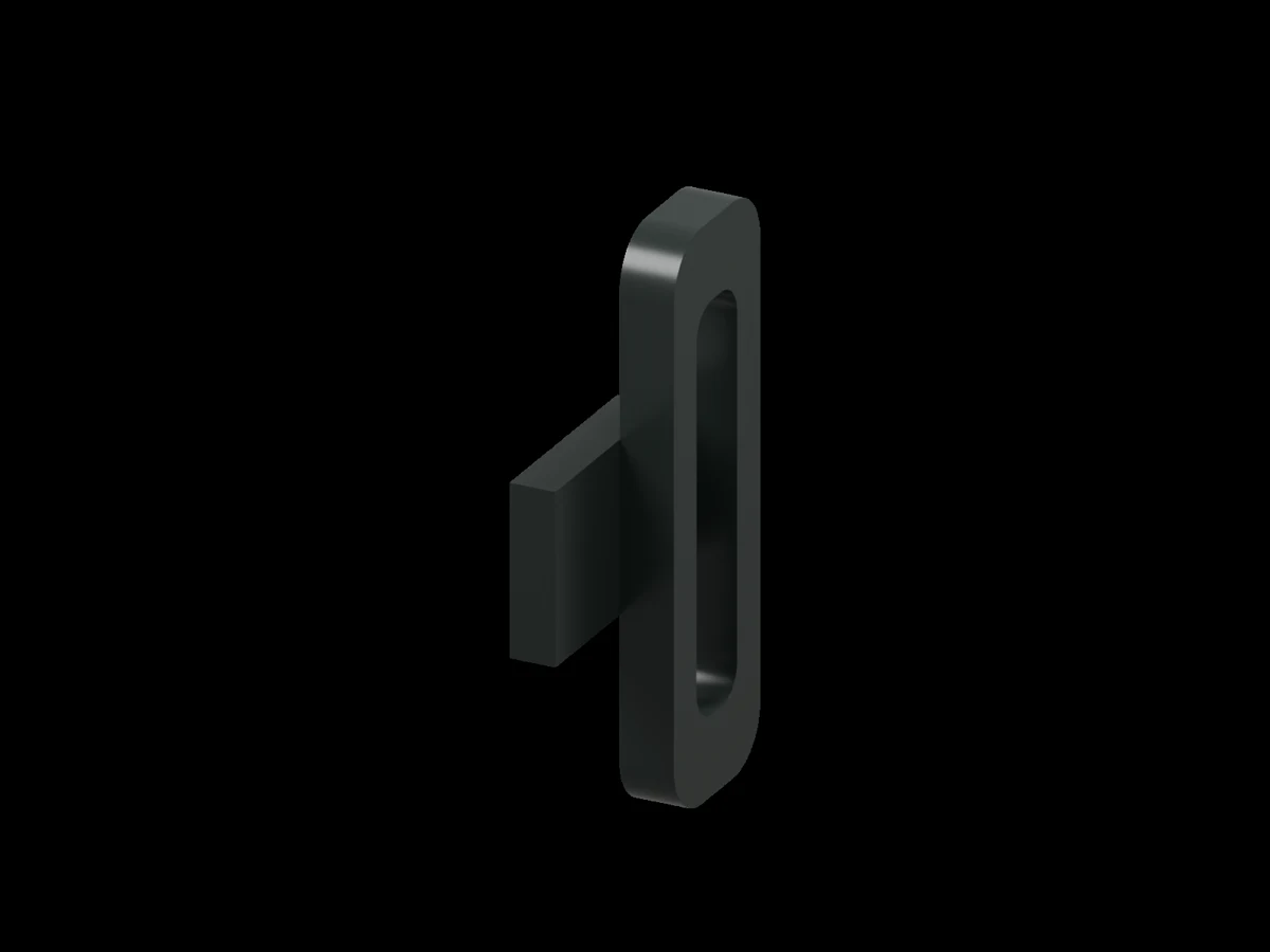
Inspect the separate two-solid handle correction candidate and the engineering limits behind it.
Treatment & service / Design study
Coarse screen
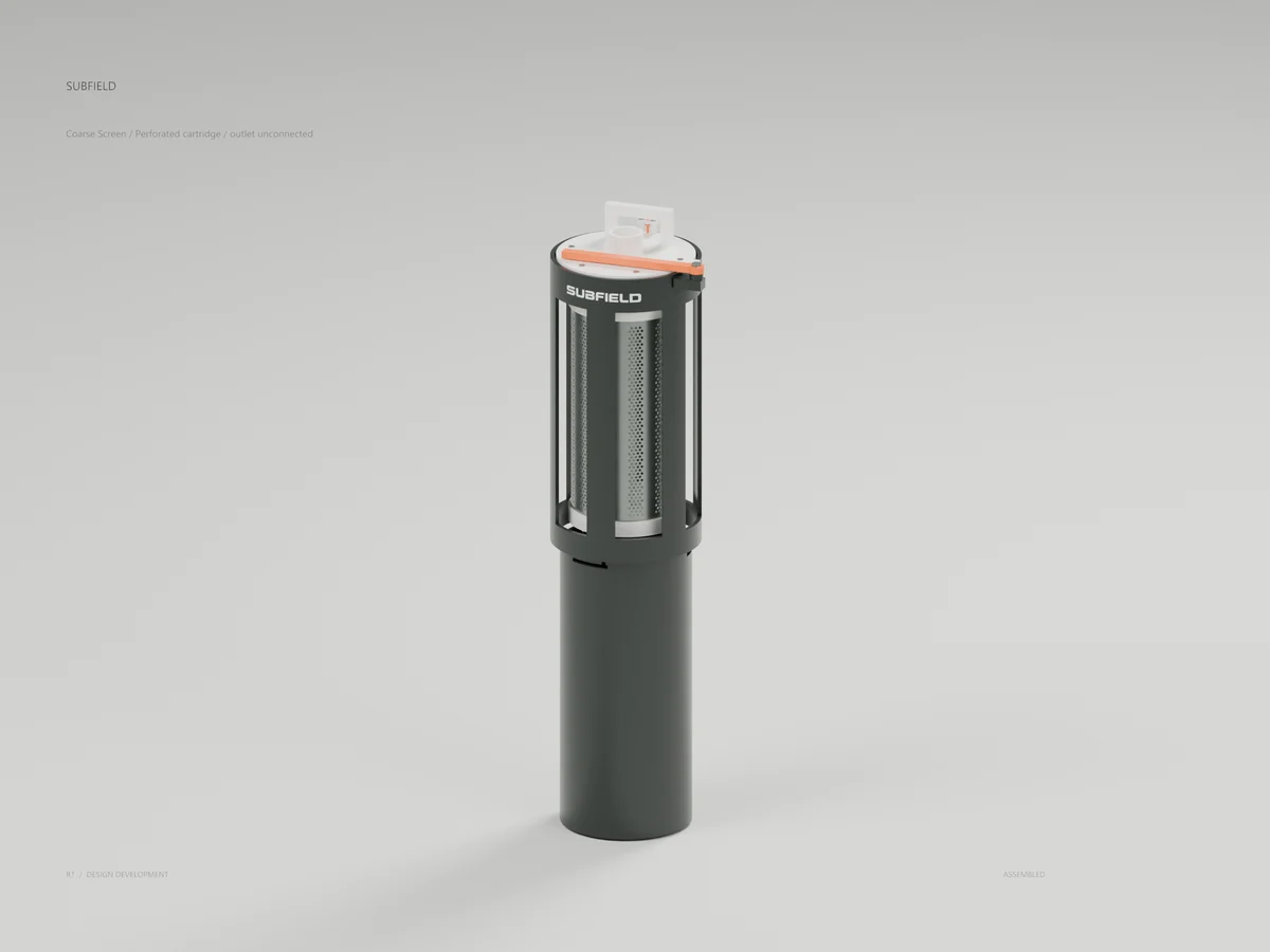
A perforated cartridge, capture mechanism and contained-removal geometry.
Treatment & service / Design study
Screen transfer
A removable bridge and vented transfer arrangement around the coarse screen.
Return to the current product.
Explore the retrofit-only platform and its compatibility, installation and service objectives.
Explore the retrofit