Connections / Design study / TANK-PENETRATIONS-R1
A considered connection.
Reinforced inlet and outlet interfaces fitted to actual tank wall cuts.
Retained development study. Dimensions, names and checks belong to this revision—not automatically to the retrofit-only product. Manufactured tank shells are deferred. No installation instruction, certification or manufacturing release is represented.
The source reasoning
Why this detail was investigated.
Inner and outer reinforcement, bonds and an edge-closeout sleeve define the interface study. Piping movement and physical leakage need their own qualification.
Read the research and limits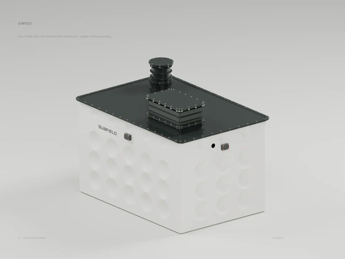
Research record
The detail behind
the study.
Source-linked work for this revision. Reported checks describe the stated model or test; physical qualification and applicability to the current retrofit remain separate.
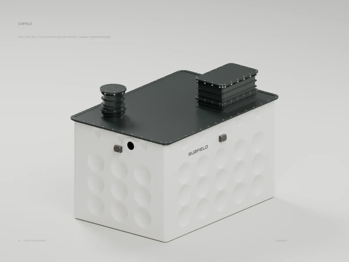
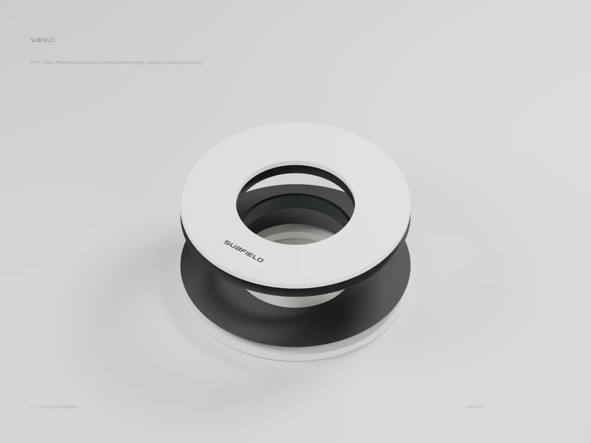
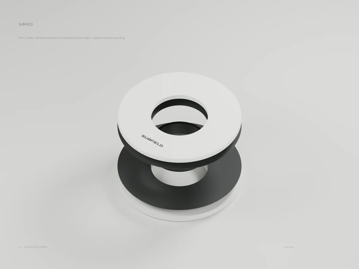
Original Subfield inlet and outlet reinforcement mounts, using actual CAD and the shared product finish family.
12 new solids. 167 CAD tests passed. Supplier hardware, complete pipe interfaces and manufacturing release remain in development.
Tank / inlet end
Tank / outlet end
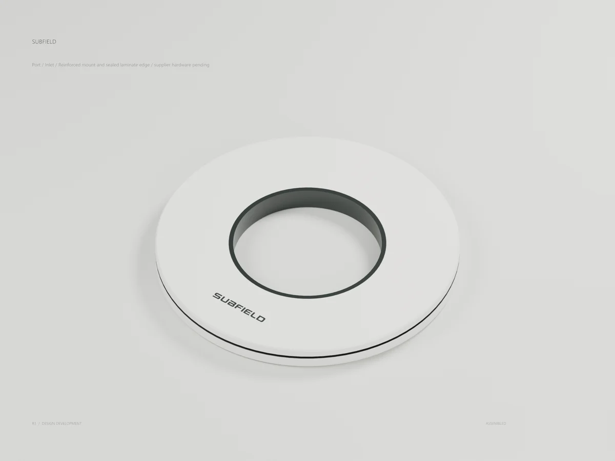
Inlet / reinforced mounting face
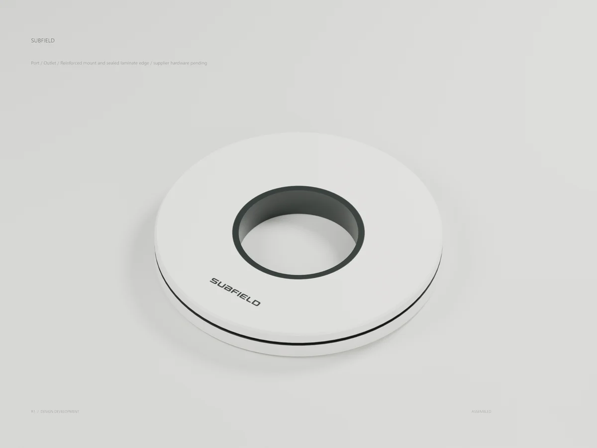
Outlet / reinforced mounting face
Inlet / separated original parts
Outlet / separated original parts
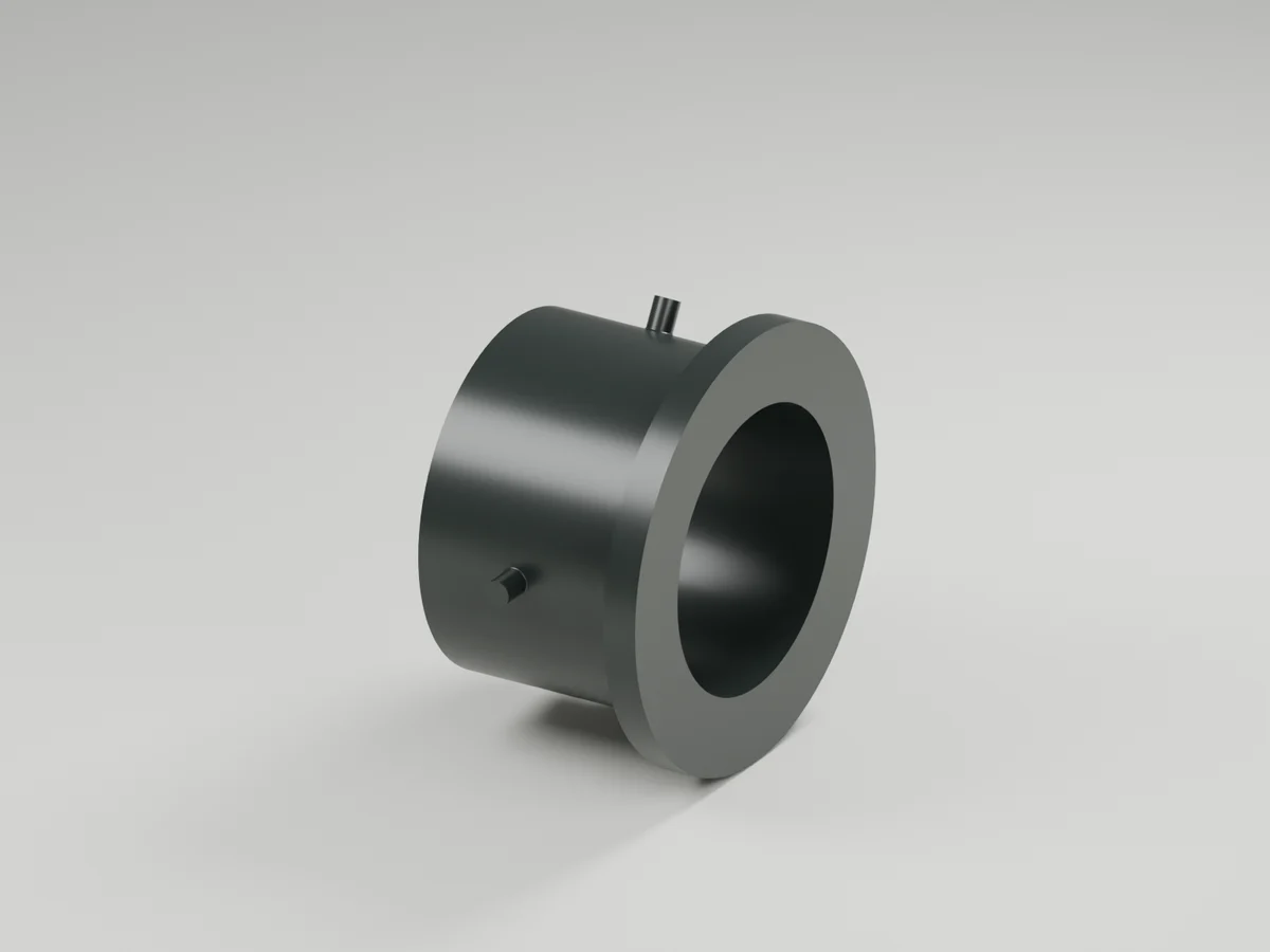
CONCEPT development package for SC-009. Two original six-part reinforcement mounts are fitted to real end-wall cuts in a separate 2,633-body tank candidate. Each mount has inner and outer doublers, two face bonds, a continuous edge-closeout sleeve and a radial bond. The existing 2 mm shell is retained outside the two circular cuts. Supplier fitting bodies, gaskets, nuts and connected piping are absent.
Verification: 167 complete CAD tests, 30 unit checks and 25 full-tank fit/export checks. Both cut volumes match a flat 2 mm wall crossing; the finished bores stay open, bond volumes contact the modified shell, new solids clear the existing tank and the eight prior exposed-side level extraction corridors remain open. STEP reimport checks preserve each body. These are nominal geometry checks, not structural, hydraulic or leakage qualification.
The first inlet position clashed with one roof rib. Its center was lowered 15 mm while retaining the complete 300 mm reinforcement diameter, leaving at least 10 mm nominal rib clearance. The preliminary inlet pipe invert is now 1585 mm. The coordinate schedule records the revised tank XYZ origin; upstream sewer, inflow, inlet tee/baffle, operating/fault levels and installation tolerances remain unresolved. The outlet has a separate 200 mm reinforcement ring.
Nominal face bonds are 0.5 mm, radial bond is 0.5 mm, sleeve wall is 4.05 mm and the complete mounting stack is 23 mm. The inner and outer GFRP doublers are 12 and 8 mm. Those values are development geometry only. Material system, layup, adhesive, machining/process, surface preparation, cure, roundness, finish, flatness, parallelism, gasket compression and assembly tooling require definition. Local shell bending, clamp loads, creep, pipe bending, thermal movement, settlement and pullout require qualification, followed by physical leakage testing under approved conditions.
The 150-scope coverage ledger records 50 partial concepts, 64 not modeled, 31 deferred and 5 non-geometric scopes. No scope becomes release-ready from these images or geometry checks. The permanent closed tank master and earlier candidate remain unchanged. Complete manufacturing design remains in progress.
Source and revision record
Source: tank-penetrations-r1/index.html
Source SHA-256: d7d0ed3ec6d9f1ec62c38134bc516a56983c33297508ba23601e970f19da6475
Geometry and images describe this development revision. Current product ratings and manufacturing release require separate qualification.
Keep exploring the research.
Connections / Development CAD
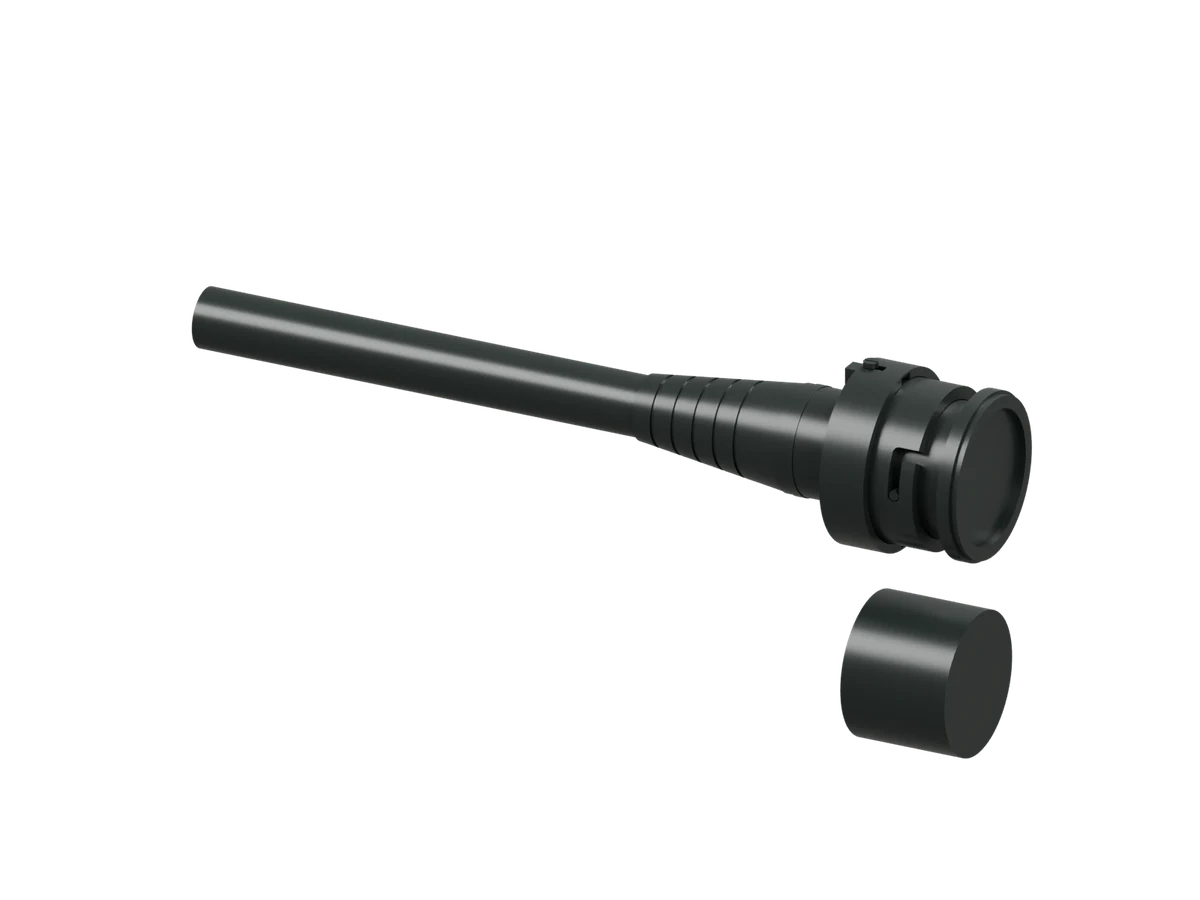
Link threaded stops
Inspect the latest complete termination geometry with modeled threaded stops.
Connections / Design study
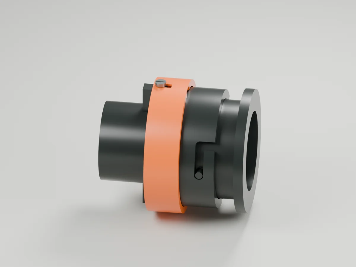
Link sleeve stops
Radial shoulder stops capture the sleeve around a proposed 3 mm release motion.
Connections / Design study
Link integral receiver
Integral bosses replace separate bayonet studs.
Return to the current product.
Explore the retrofit-only platform and its compatibility, installation and service objectives.
Explore the retrofit