Engineering records / Engineering record / ROOF-PERIMETER-R1
Roof Perimeter R1.
Geometry, analysis and remaining engineering work for Roof Perimeter R1.
Retained development study. Dimensions, names and checks belong to this revision—not automatically to the retrofit-only product. Manufactured tank shells are deferred. No installation instruction, certification or manufacturing release is represented.
The source reasoning
Why this detail was investigated.
Development geometry. The complete tank/system is not ready for manufacture.
Read the research and limits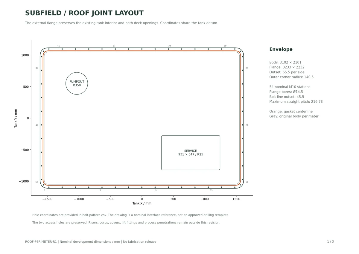
Research record
The detail behind
the study.
Source-linked work for this revision. Reported checks describe the stated model or test; physical qualification and applicability to the current retrofit remain separate.
Subfield roof perimeter joint — R1
Development geometry. The complete tank/system is not ready for manufacture.
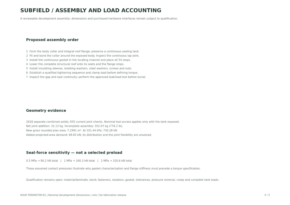
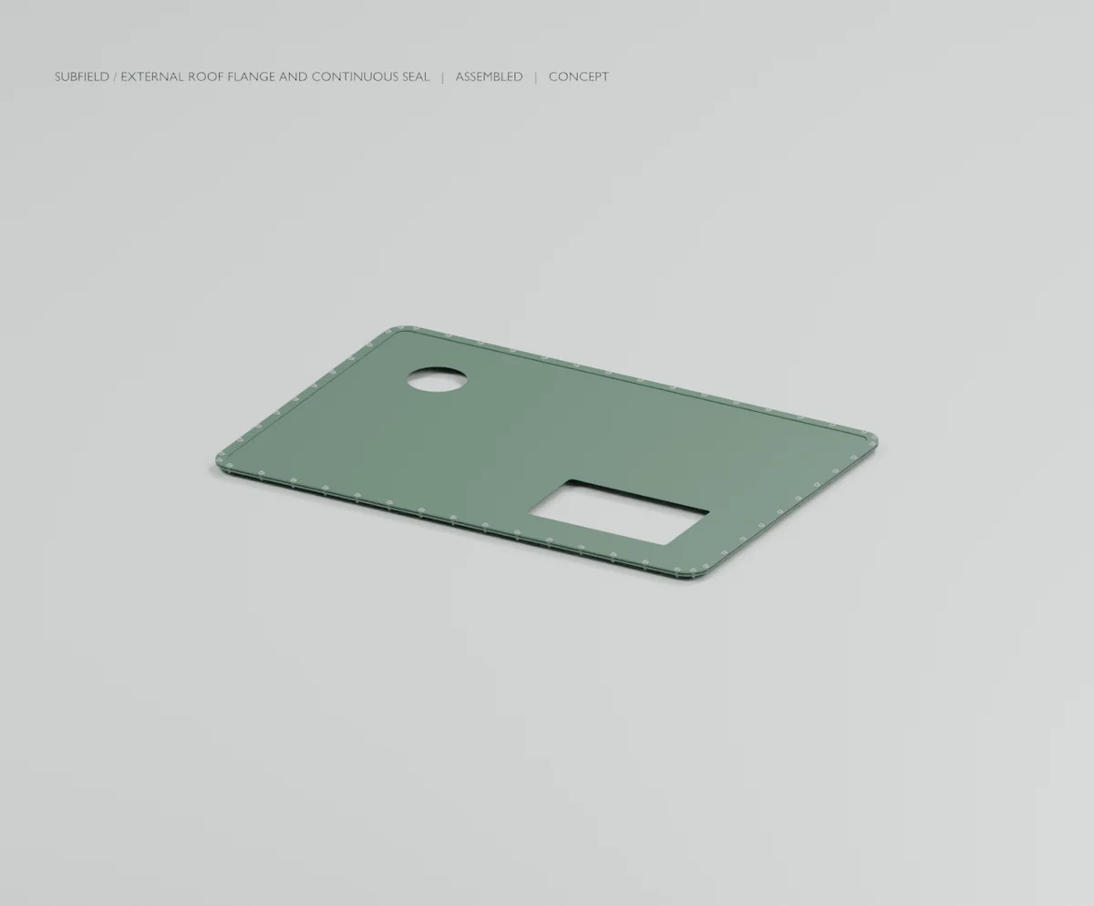
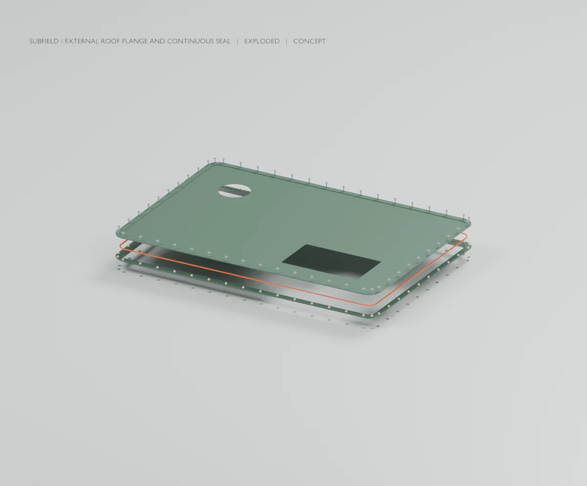
This revision replaces the deck with a flanged deck and adds an external bonded collar, a continuous gasket and 54 insulated fastener stations. The combined assembly contains 1618 separate solids. The original body is 3102 × 2101 × 1850 mm; the outward flange changes the plan envelope to 3233 × 2232 mm. Central deck top remains Z1860; flange laminate top is Z1867 and bolt-head top is Z1876.9. A conservative 4572 mm cover from the flange puts study grade at Z6439. Those are design-study datums, not an installation depth rating.
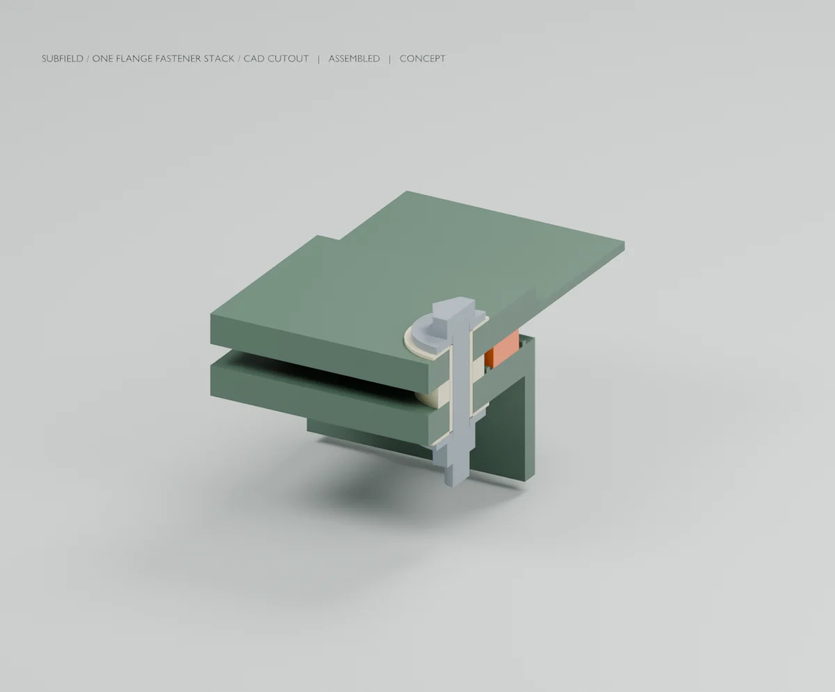
- vessel-with-perimeter-joint.step: complete current geometric assembly, in mm. Retained members use their input labels, with indexed occurrences where the input repeated a label. - perimeter-joint-assembly.step: the replacement deck and all added joint parts. - perimeter-collar.step, perimeter-collar-bond.step, roof-deck-flanged.step: individual custom geometry. - gasket-free-state.step: separate nominal free gasket loop at local Z0; it is not the compressed installed state. - perimeter-joint-review.pdf: three reference sheets: plan, stack section and assembly/load accounting. - bolt-pattern.csv: all station coordinates and nominal flange bores. No released drilling tolerance is implied. - joint-part-takeoff.csv: geometric volumes and mass at assumed material-group densities; not a purchasing BOM. - .blend, .glb, views/ and detail/: CAD-derived review visuals. The local view cuts the actual joint at a bolt axis. The exploded arrangement is for inspection, not a qualified lift or service procedure. - perimeter-joint-record.json: geometry, contact, tool/service checks, input occurrences, assumptions, source hashes and load-area accounting. - controlled-input/: exact upstream STEP, report and artifact manifest required to reproduce this revision. - current-cad-source.zip: editable generators, tests, parameters and pinned dependency files.
Verification and engineering implications
The current generator passed 935 checks, with no reported volumetric interference. Checks include preservation of the original deck, separate solids after STEP reimport, continuous gasket free/compressed volume, gasket channel containment, contact chains, sleeve end clearance, local socket corridors, wet-module extraction and the full vertical pumpout corridor. Regression checks preserve repeated input labels as separate occurrences and copy parts without recursively copying their parent assembly: the prior STEP has 24 objects labeled COMPOUND, all retained here. The full CAD suite passed 89 tests in 28.93 seconds. The review drawings and Blender images were visually inspected before packaging.
The joint adds a net 31.13 kg. The incomplete combined assembly is 352.07 kg (776.2 lb). This exceeds the approximately 500 lb objective before the remaining components are added.
The enlarged rounded outline is 7.1991 m². At the retained 101.44 kPa study pressure, gross projected-area demand is 730.28 kN, an increase of 69.65 kN over the previous rounded outline. Opening tributary loads are retained. This is area accounting, not a solved load distribution or a new roof-strength result. Earlier roof/post calculations are not evidence for this enlarged joint assembly.
Joint definition and remaining work
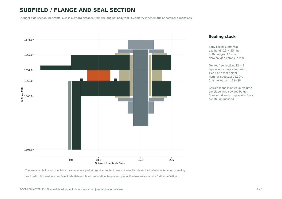
The bonded collar has a nominal 6 mm wall, a 45 mm high × 0.5 mm lap-bond layer and a 10 mm flange. The integral roof flange is also 10 mm. Discrete nonconducting stops define the 7 mm nominal sealing gap. A custom continuous gasket with a 12 × 9 mm free section has 22.22% nominal squeeze; its installed rectangular envelope is widened to conserve volume. Actual bulging, swelling, surface contact and seal force are not predicted. Both free and compressed states have separate geometry.
Each station models a nominal M10×50 screw envelope, nut, two steel washers, two isolation washers, an insulating sleeve and a separate compression stop. The sleeve is 28 mm long and ends 0.5 mm short of each steel washer, so it cannot bypass the nominal flange clamping path. The cited Bossard screw dimensions are a supplier reference; the complete hardware set has no approved purchasing specification. Simplified threads/chamfers, stock laminate interfaces and the nominal section are insufficient for fabrication release. No tightening torque is specified before clamp-load, gasket, creep and flange qualification.
Complete laminate/ply continuity, mold radii, material grades, continuous-gasket manufacture, collar surface preparation/bond procedure, flange stiffness, thread locking, corrosion/isolation, tolerances/flatness, handling, inspection and leak/load tests. The collar adds an external bond that is part of the water boundary. All actual sealing and load capacity remain unverified. Roof disassembly requires the tank to be exposed; routine buried servicing uses the two access openings and their still-unfinished curbs, risers and covers.
The full remaining system scope is tracked in the adjacent manufacturing handoff: process partitions/equipment, wet docks, actual electrical packaging and services, lift/level interfaces, 1500/3000 gallon variants, tooling and controlled release are not completed by this joint revision.
Extract current-cad-source.zip into this package folder. From its cad directory:
Render the generated scene.json using wet_render.py; render the detail/scene.json into a separate detail folder. Blender 5.2.1 LTS was used for these outputs. The source requires the exact pinned upstream STEP. Re-exporting its earlier source is a new input snapshot and must be checked and explicitly rebased rather than bypassing the hash check.
Product requirements: current owner decisions and structural register. Hardware family reference: Bossard BN624; exact screw example URL is retained in the parameter set. Parker's gasket guidance identifies the dependence on material, pressure, temperature, compression and flange hardware; it does not qualify this proposed gasket or assign its dimensions.
Source and revision record
Source: roof-perimeter-r1/READ-ME.md
Source SHA-256: 17d335f978a163ebc329d53ca3e42bb64985a70b3df7bf3c5e11e7f0b8c17496
Geometry and images describe this development revision. Current product ratings and manufacturing release require separate qualification.
Return to the current product.
Explore the retrofit-only platform and its compatibility, installation and service objectives.
Explore the retrofit