Product family / Design study / PRODUCT-RENDER-LIBRARY-R1
Explore every modeled view.
The broad collection of tank, control, flow and service studies.
Retained development study. Dimensions, names and checks belong to this revision—not automatically to the retrofit-only product. Manufactured tank shells are deferred. No installation instruction, certification or manufacturing release is represented.
The source reasoning
Why this detail was investigated.
Assembled, sectioned and separated views expose different design questions. Models are partial development work, not finished manufacturing designs.
Read the research and limits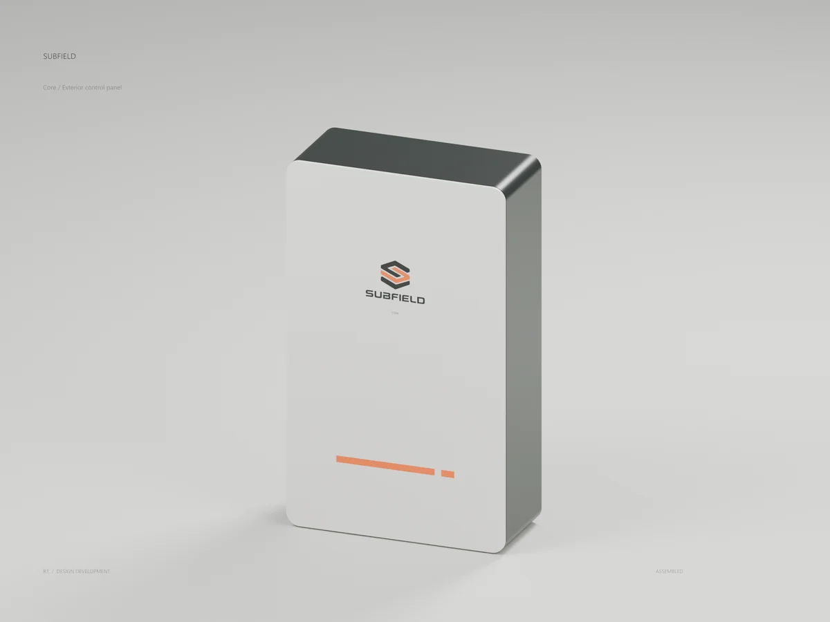


Research record
The detail behind
the study.
Source-linked work for this revision. Reported checks describe the stated model or test; physical qualification and applicability to the current retrofit remain separate.
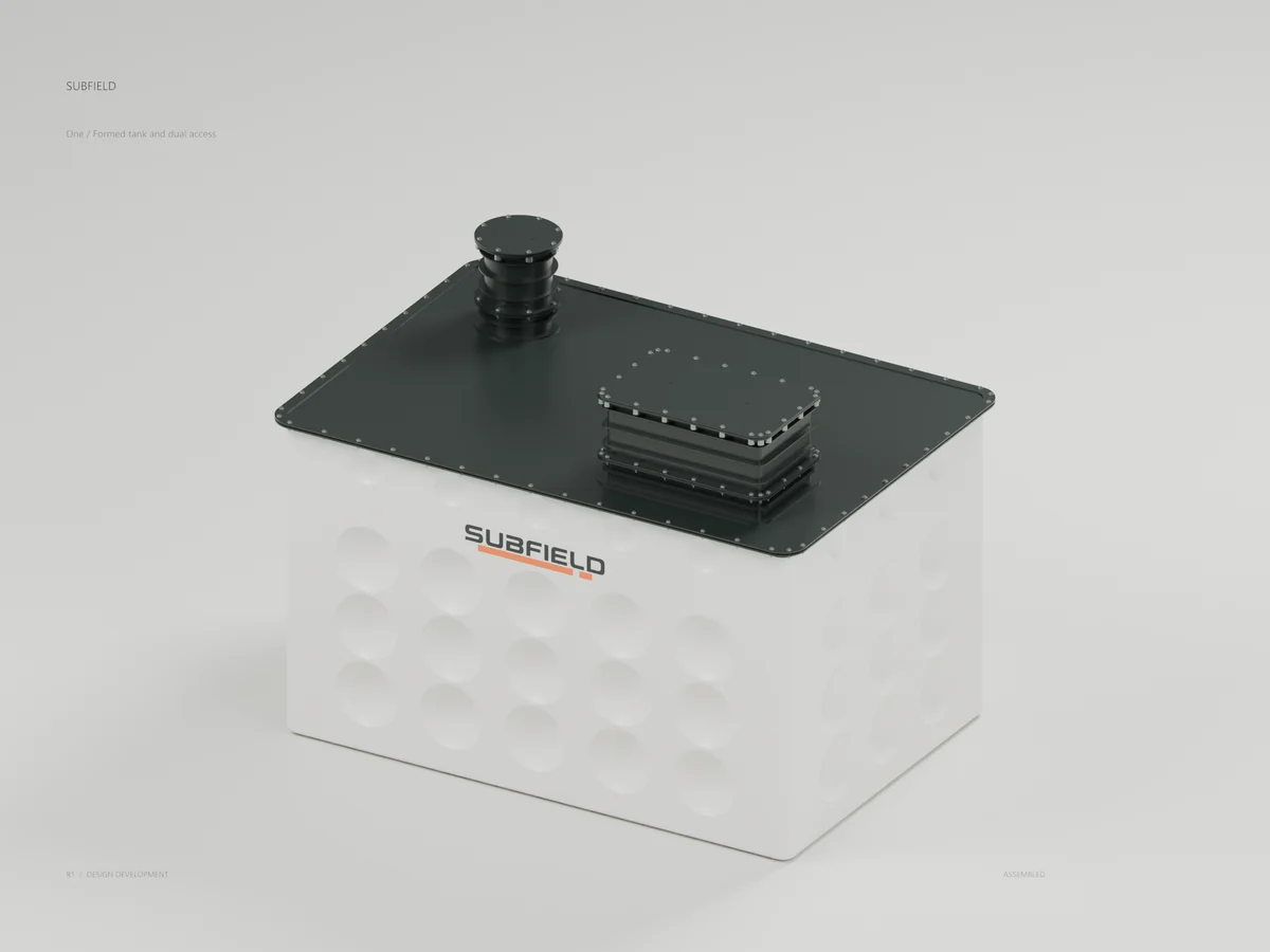
One
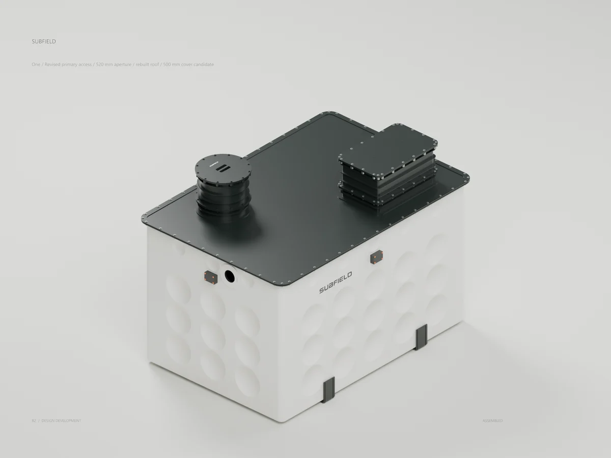
Formed lower vessel, Graphite roof and two access points. The Chalk shell carries the selected wordmark and split Fieldline on its front surface. Current 500 mm cover configuration. Process connections and structural release remain open.
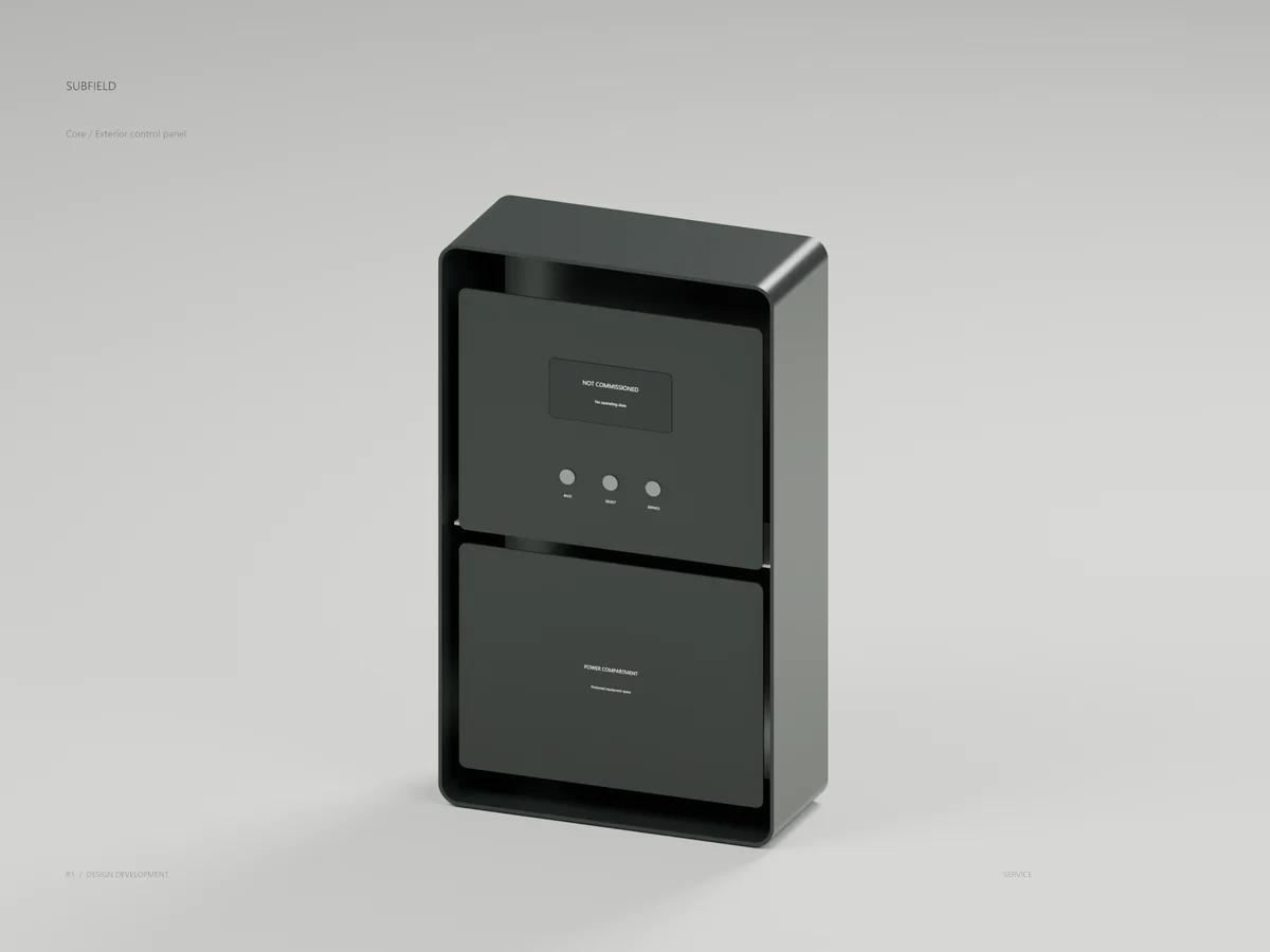
Core
Chalk weather cover over a Graphite enclosure. The service view reveals a stationary interface faceplate above a separate power-compartment cover. 360 x 600 x 150 mm enclosure study. Supplier electronics, seals and attachment details remain open.
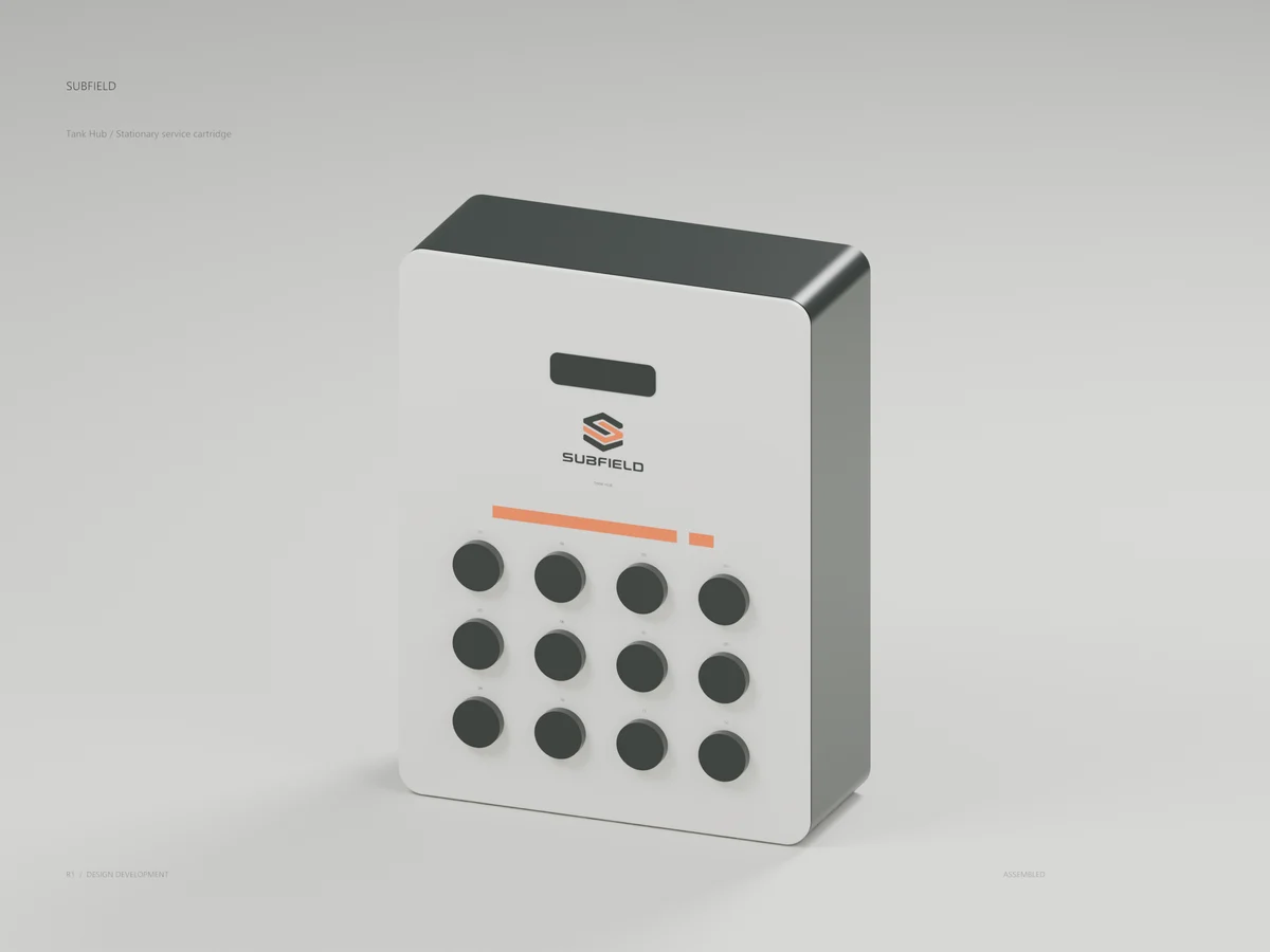
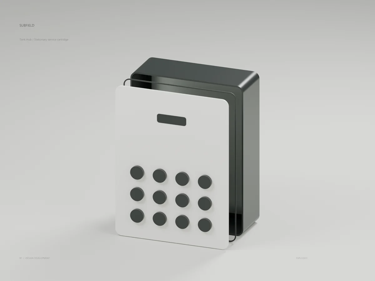
Tank Hub
A stationary carrier supports the removable housing independently of the tank lid. Twelve capped branch envelopes and numbered positions organize its service face. 310 x 410 x 115 mm packaging study. Electronics, contacts, cap retention and tank mounting remain open.
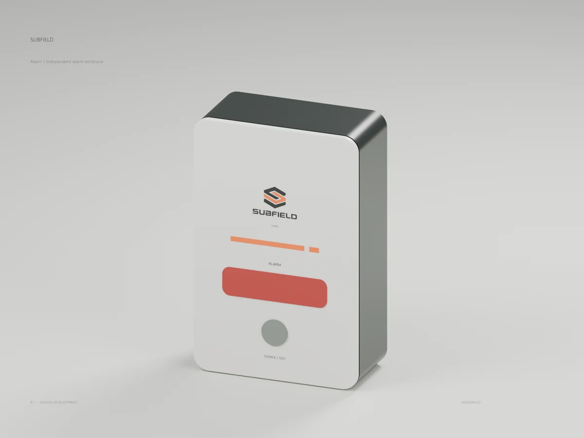
Alarm
A separate enclosure gives the alarm its own physical presence. A red optical insert is distinct from the orange brand stripe; the silence/test key stays visible. 150 x 230 x 65 mm enclosure study. Actual annunciators, detection logic and reserve power remain open.
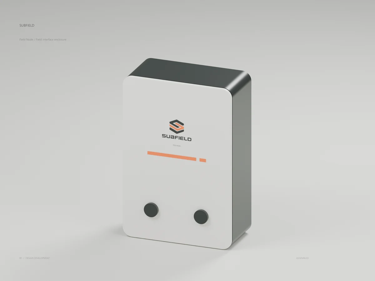
Field Node
The enclosure repeats the family corner radii, cover seam and recessed working-surface color. Two closed entry envelopes sit below the identity band. 190 x 280 x 85 mm study. Field electronics, selected entries and site configuration remain open.
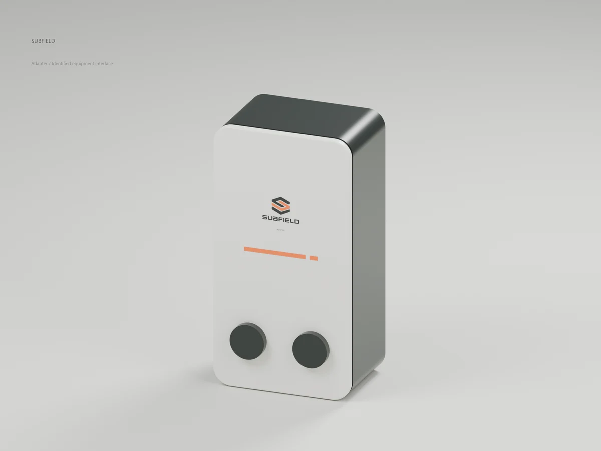
Adapter
A compact member of the same enclosure family, with a clear identity area and two closed connection envelopes. 95 x 180 x 58 mm study. Actual drivers, supplier interfaces and thermal design remain open.
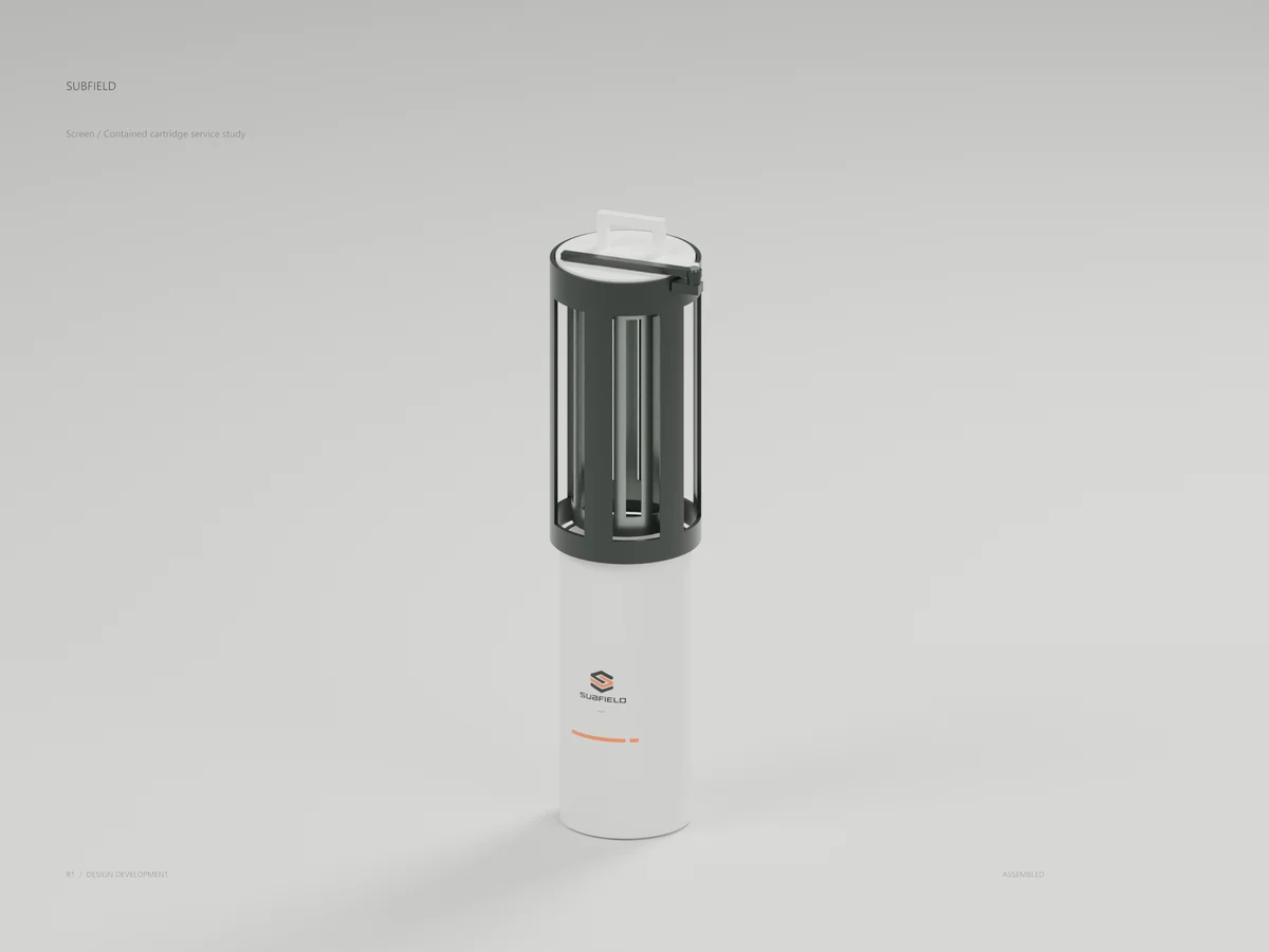
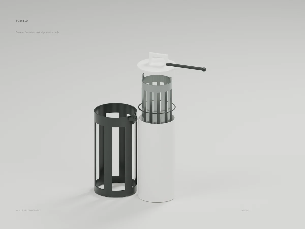
Screen
The existing service assembly has a keyed head, pivoting retainer, cartridge support and capture sleeve. Its exploded view separates the actual CAD components. The supplied filter element, hydraulic isolation, sleeve actuation and seals remain open. Large support windows are not a filter cut size.
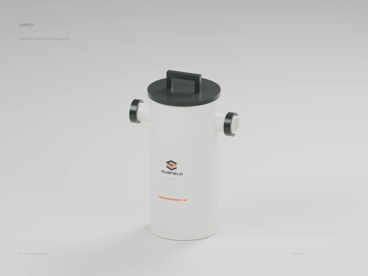
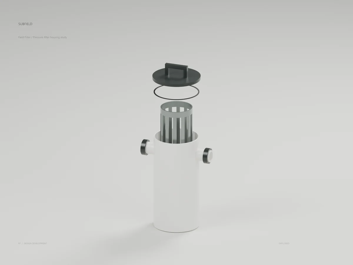
Field Filter
A cylindrical Chalk housing with two open pipe interfaces, a separate Graphite head and an internal element carrier. The logo follows the curved surface. Filter element, head retention, hydraulic isolation, bypass sealing and pressure qualification remain open.
Treat
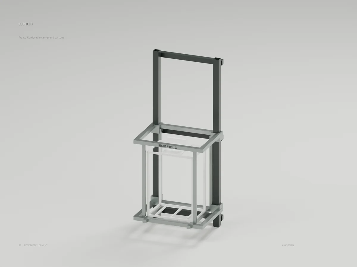
Fixed guides remain while the wet carrier and cassette are removed. The restrained wordmark fits the existing front frame surface. The cassette is empty. Biological medium, distributor, collector and retention details remain open.
One / Inside
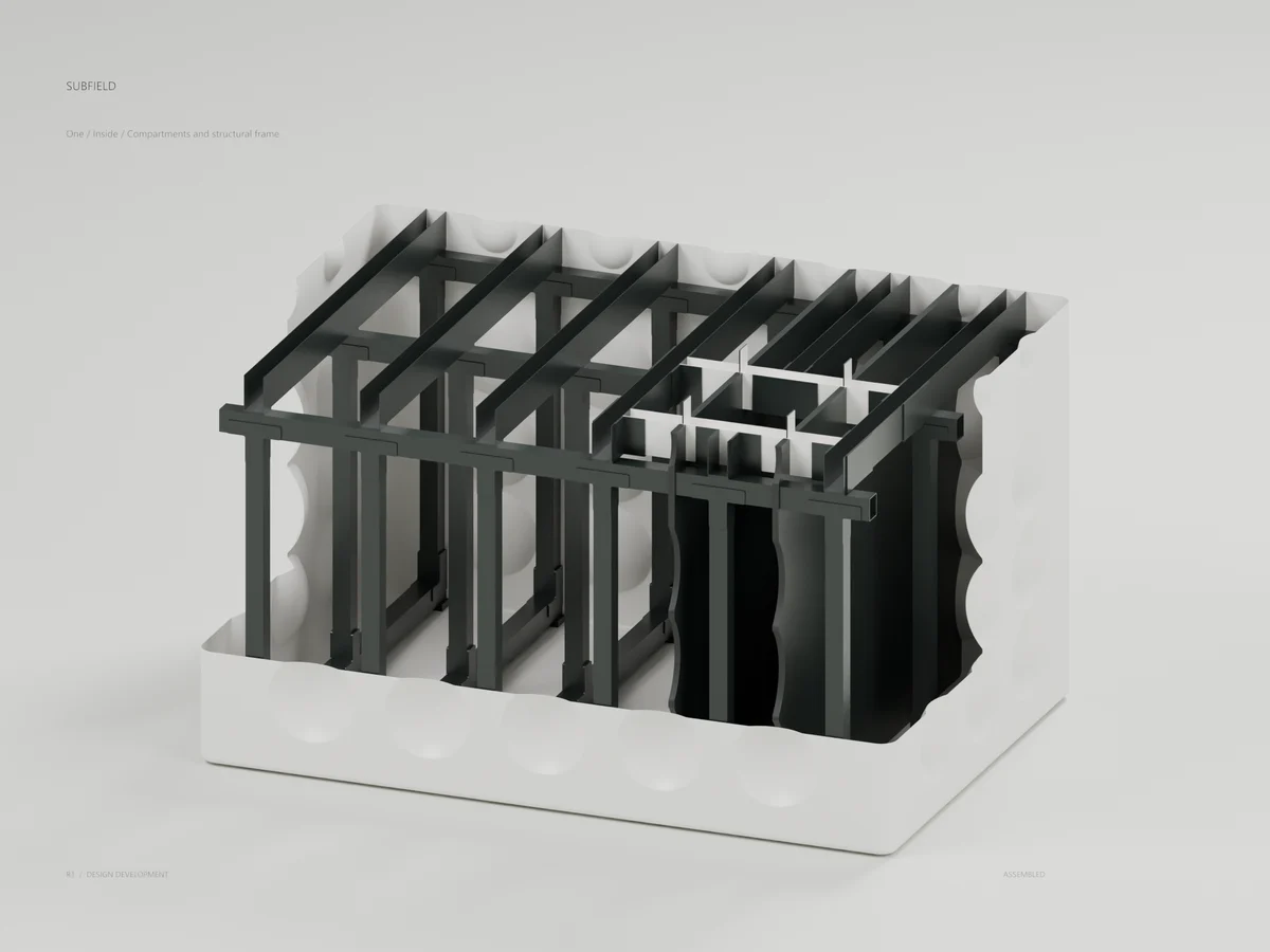
A CAD cutaway exposes the three chamber regions and retained structural frame. The included full tank STEP keeps all 2308 solids uncut. Partitions are currently closed. Transfer paths, actual equipment and final usable capacity remain open.
Access
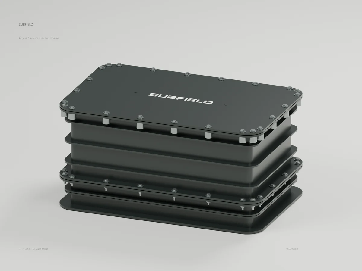
The service adapter, riser and cover share controlled datums with the tank. Captive hardware and the secondary grate remain in the CAD assembly; the top wordmark clears the lift bores. The included access STEP also contains the pump-out branch. Whole-assembly qualification remains open.
Pump Dock
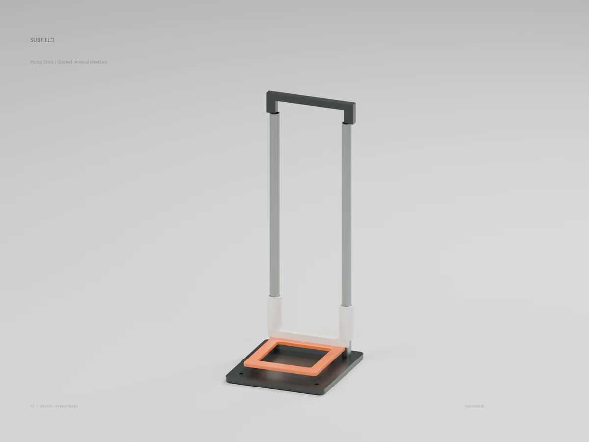
Hollow guide rails, sliding collars and a carrier frame form the retrieval study. Revised cradle clearances remove the rail clashes found in the assembly audit. Pump selection, hydraulic coupling, tank mounting, retention and lifting loads remain open.
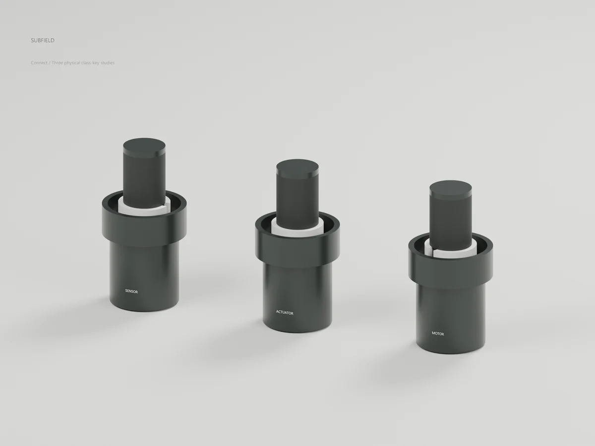
Connect
One mechanical handling family with three different key orientations. Matching mechanical shells clear; mismatched class shells interfere in the geometry test. Contacts, locking, seals and electrical ratings are absent. This is a mechanical class-key study.
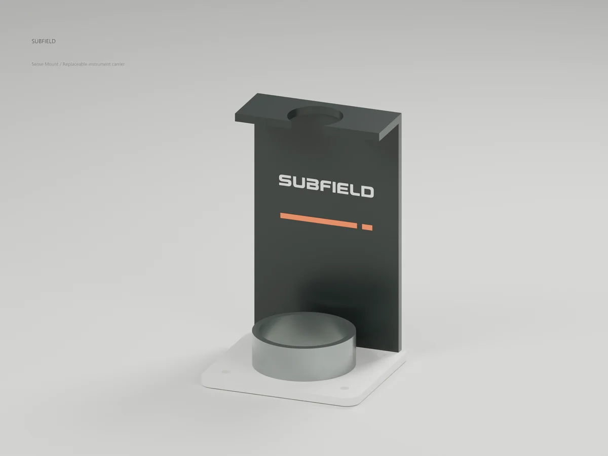
Sense Mount
An upright bracket provides instrument apertures and a replaceable metallic saddle. The identity sits on the solid upright, clear of the sensor openings. Exact supplier sensor geometry, clamping and installed location remain open.
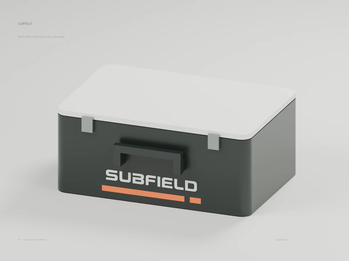
Service Kit
A Chalk lid, Graphite body, separate latch envelopes and contacting handle brackets. The wordmark and Fieldline sit below the grip without being obscured. Tool layout, lining, hinge/latch engagement and attachment qualification remain open.
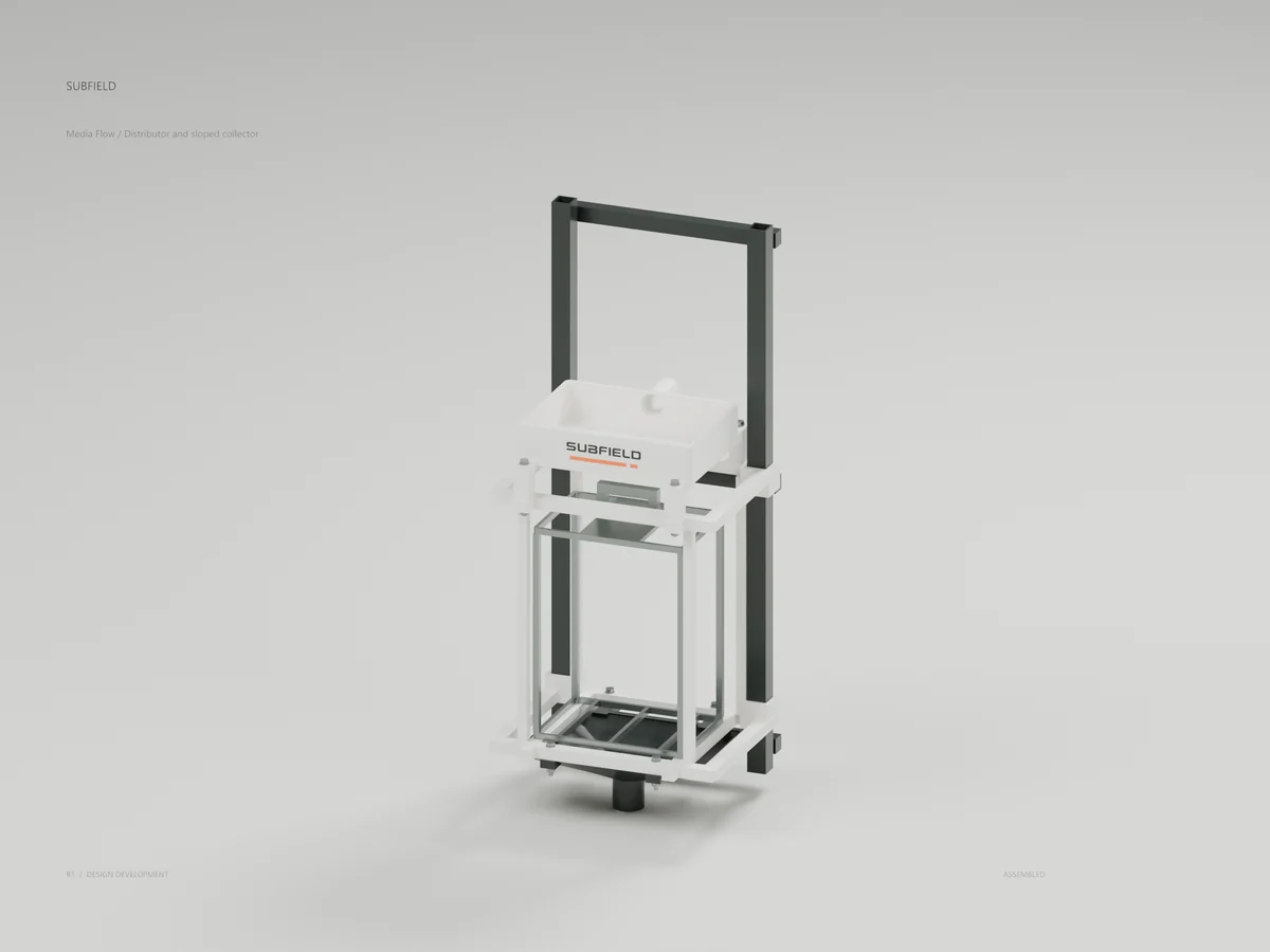
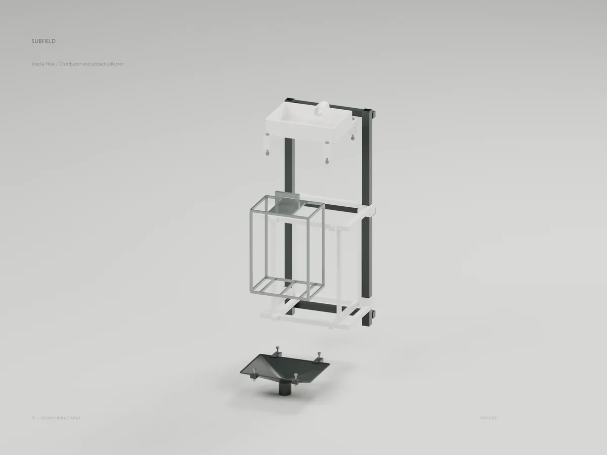
Media Flow
A nine-port distributor and sloped collector complete the geometry around the empty media cassette. Actual media, plumbing and operating performance remain in development.
Flow Distributor
An open tray distributes incoming flow through nine outlets. Leveling, fouling and wetting uniformity require physical tests.
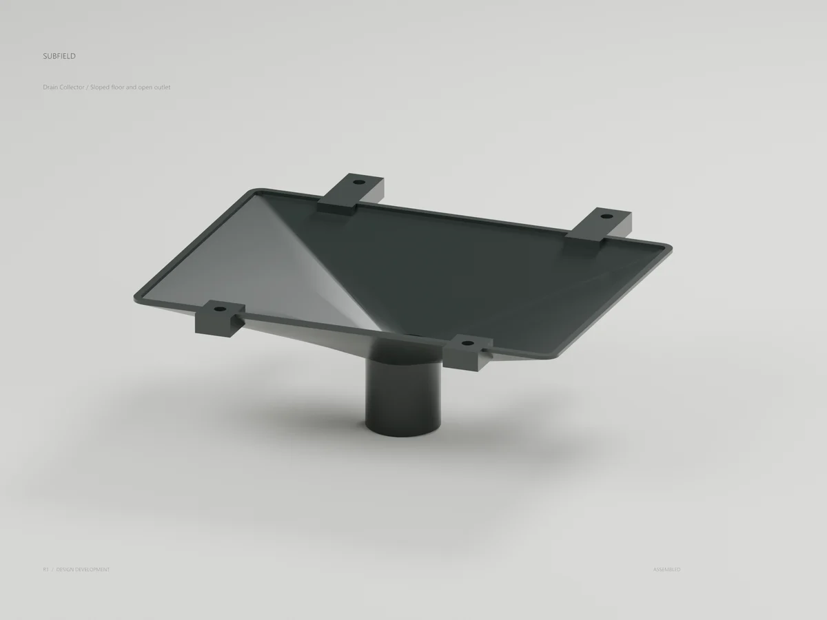
Drain Collector
A sloped collector directs flow toward one open drain. Material, cleaning and connected discharge details remain open.
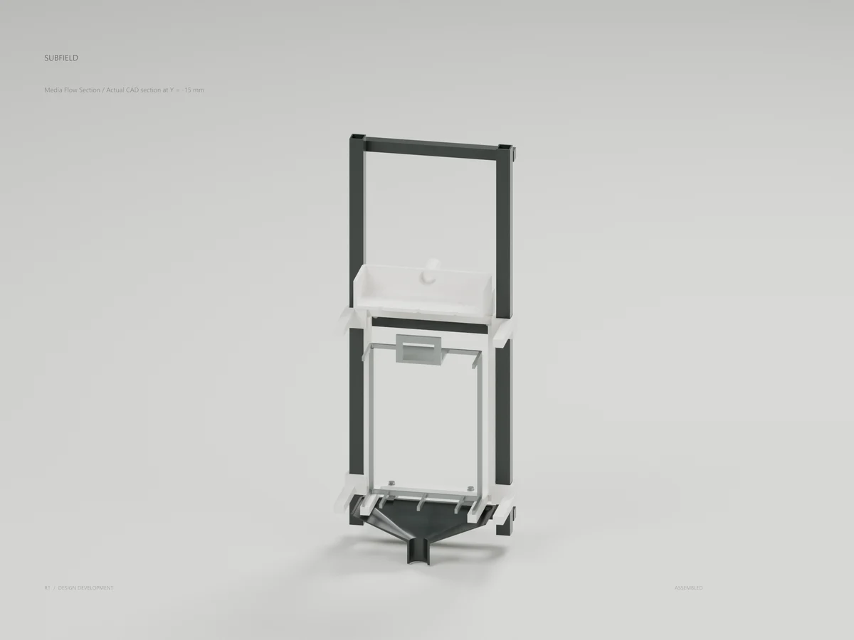
Media Flow Section
A cut through the actual CAD exposes distribution and collection around the empty cassette. This earlier arrangement predates the raised receiver alternative.
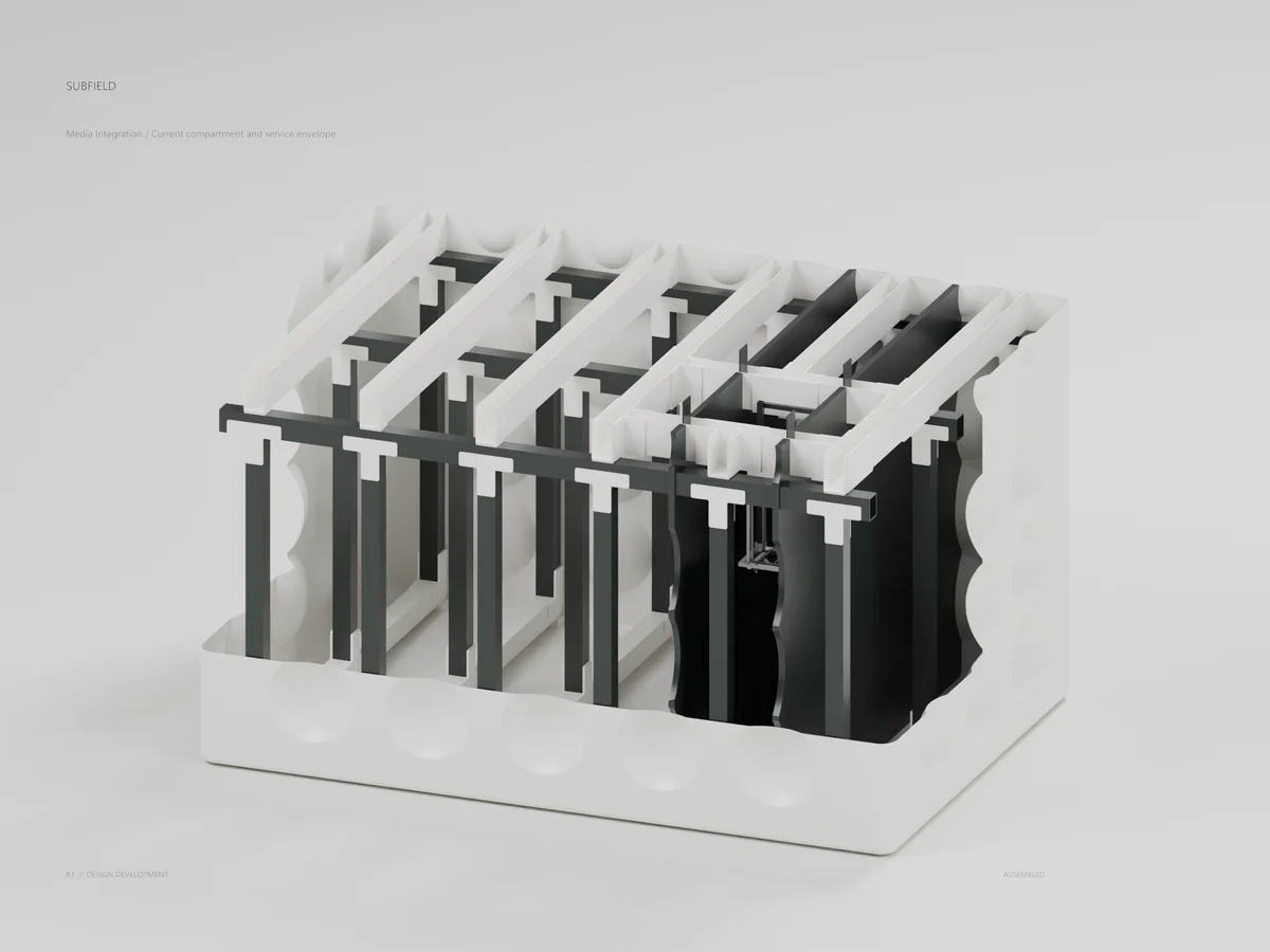
Media Integration
Current compartment and service envelope
The earlier media assembly fits the closed-partition tank. The newer receiver alternative raises this assembly to make room for the gravity discharge.
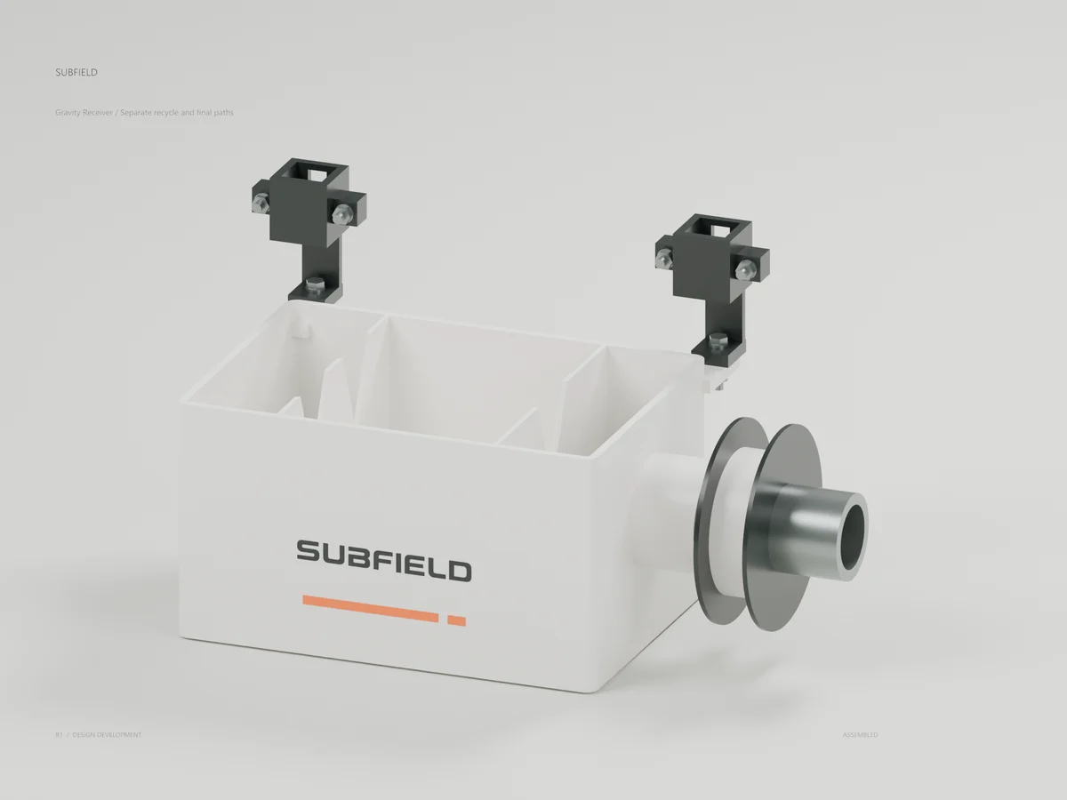
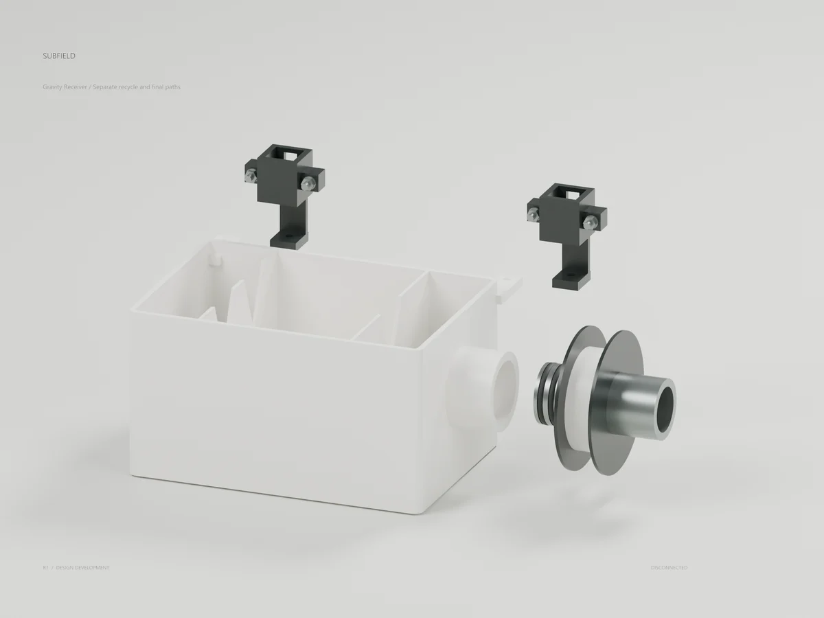
Gravity Receiver
One removable body separates recycle and final paths. Flow calibration, service isolation, seal qualification and cleaning remain in development.
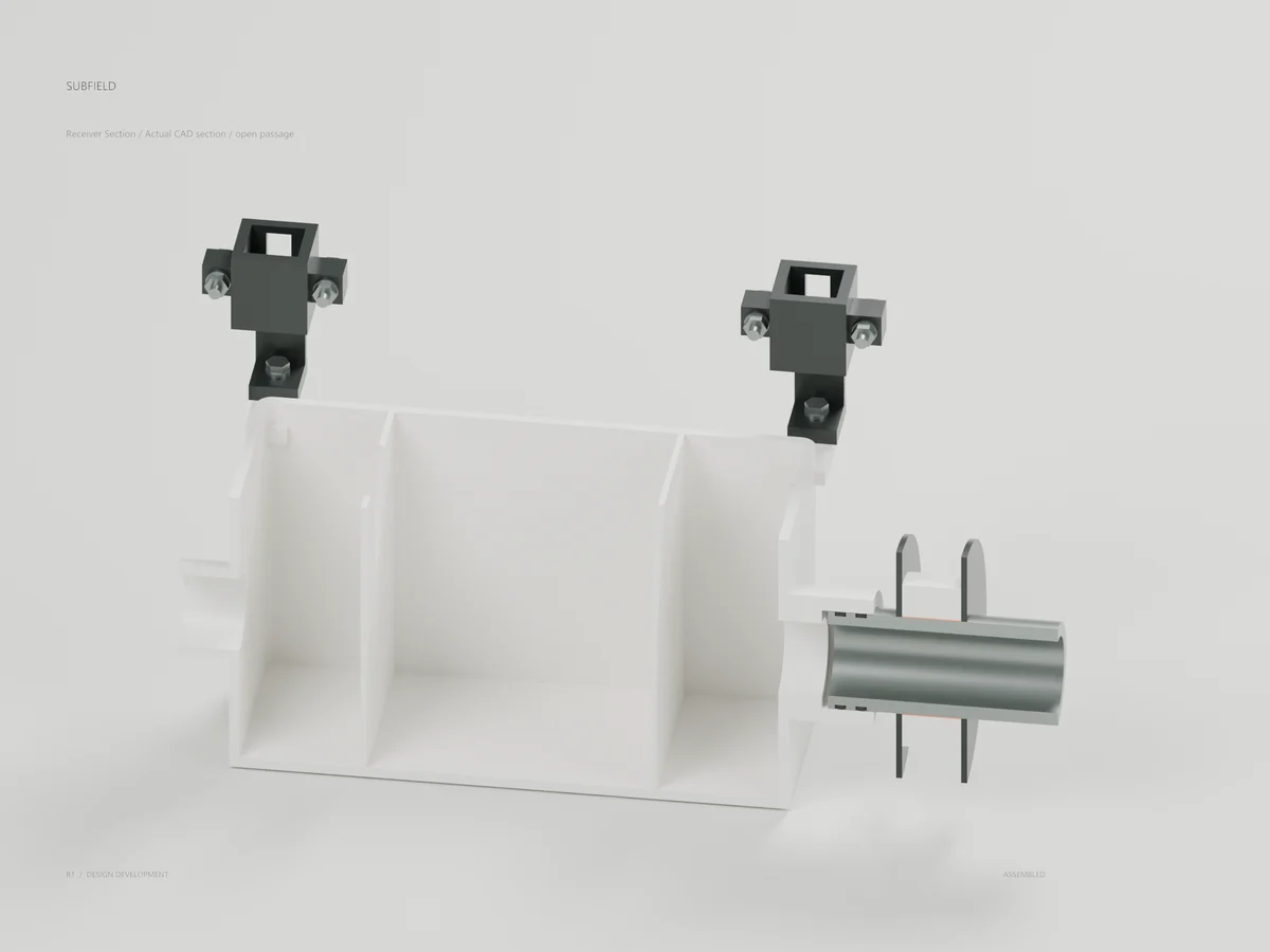
Receiver Section
A CAD section exposes the common pool, divider notches and open passages. The compact weirs have no calibrated flow ratio.
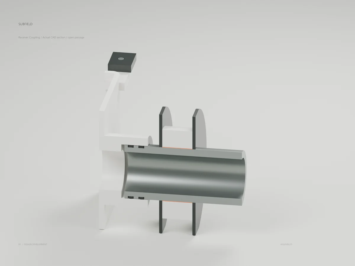
Receiver Coupling
The section reveals two seal studies and the sleeve interface. Free seal selection, tolerances and leakage qualification remain open.
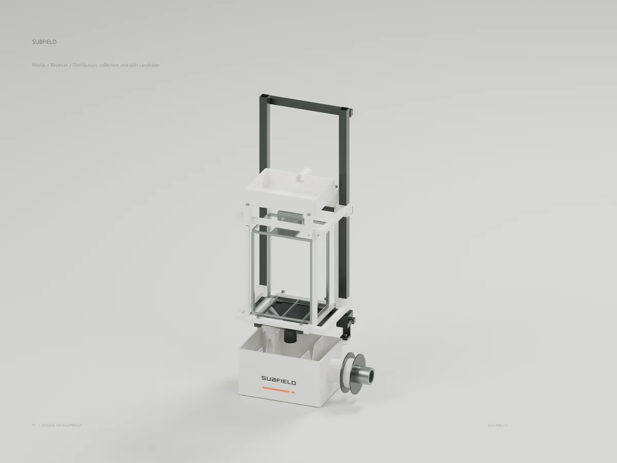
Media + Receiver
Distribution, collection and split candidate
The distributor, empty cassette and collector sit above the removable receiver on one backbone. Actual media, supply plumbing and grade handling remain open.
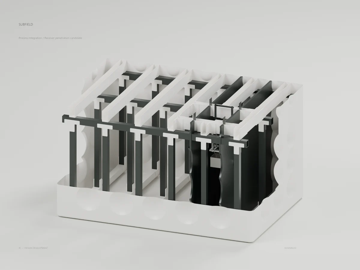
Process Integration
A separate tank candidate connects the receiver through the actual partition layers. Service isolation and penetration qualification are unresolved; the closed tank master stays unchanged.
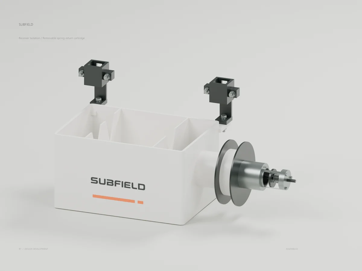
Receiver Isolation
A new receiver alternative adds a retrievable spring-return cartridge. Nominal close-before-disconnect geometry is checked; physical isolation remains unqualified.
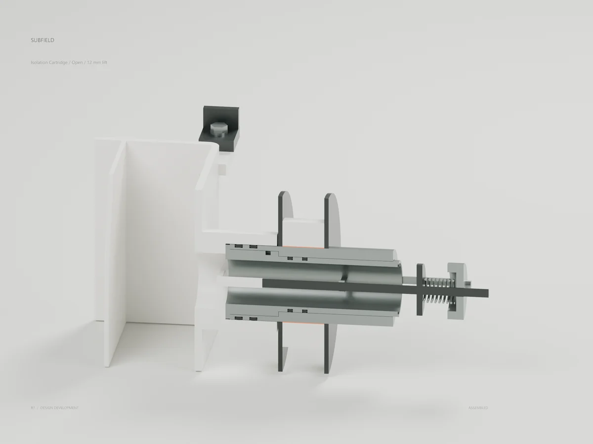
Isolation Cartridge
The receiver probe holds the poppet 12 mm open. The CAD section shows the stem guide, seals and spring; flow loss and fouling require tests.
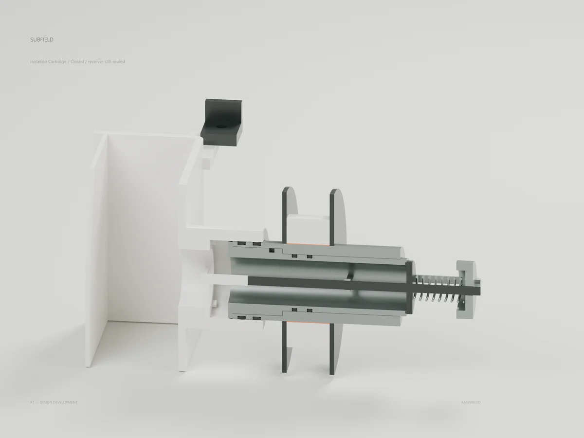
Isolation Cartridge
Nominal closure occurs while both socket seals remain engaged. The 1.5 mm margin requires tolerance, contamination and failure-response qualification.
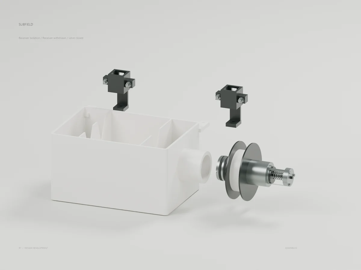
Receiver Isolation
The receiver withdraws 65 mm left and 10 mm forward. The valve remains in the fixed fitting; actual leakage and grade handling remain unresolved.
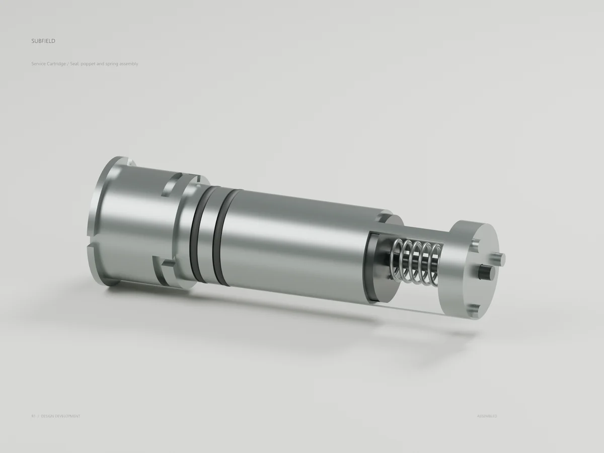
Service Cartridge
The bayonet cartridge carries the working seals, poppet and spring. Removal requires separate chamber isolation, a developed grade tool and captured drainage.
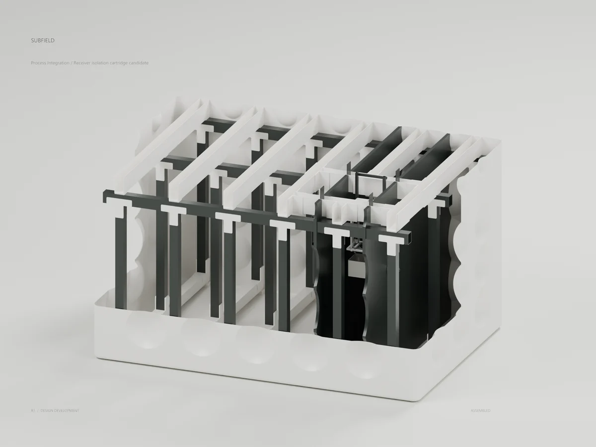
Process Integration
Receiver isolation cartridge candidate
The revised assembly and extraction lanes clear the shallow tank with 30 mm external allowance. The closed permanent master remains unchanged.
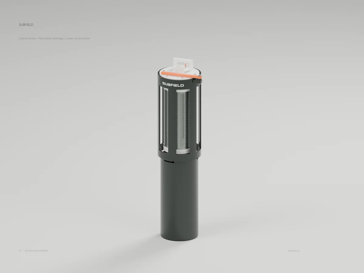
Coarse Screen
Perforated cartridge / outlet unconnected
The revised F1 assembly adds an actual perforated insert and closed base. The top outlet remains unconnected; this is not an operating installation.
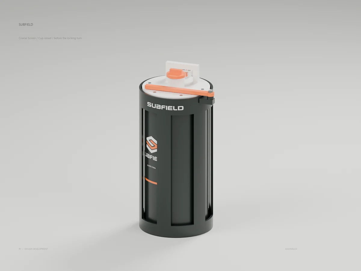
Coarse Screen
Cup raised / before the locking turn
The cup raises around the cartridge while the head remains seated. Grade actuation and independent isolation still need development.
Coarse Screen
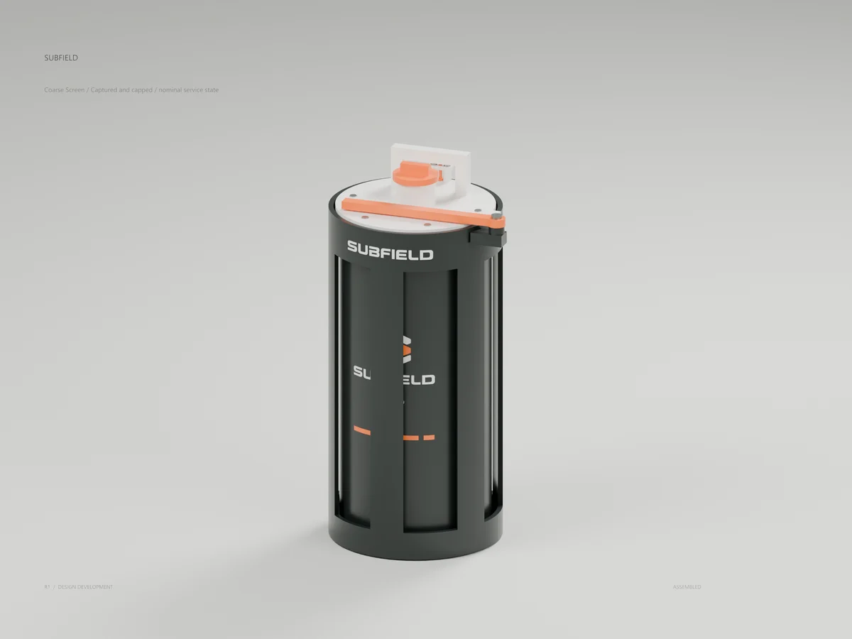
Captured and capped / nominal service state
A 30-degree turn engages three pins; a captive plunger blocks reverse rotation. Compressed ring studies and a separate cap define a nominal captured boundary.
Coarse Screen
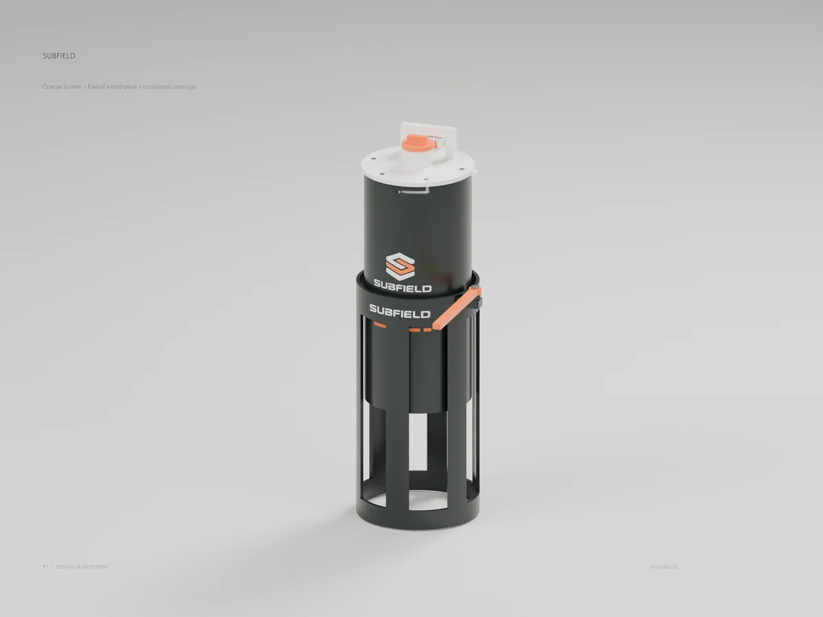
Partial withdrawal / contained cartridge
The retained cup and cartridge move together during withdrawal. Actual gloved operation, wet loads, spills and long guides remain unqualified.
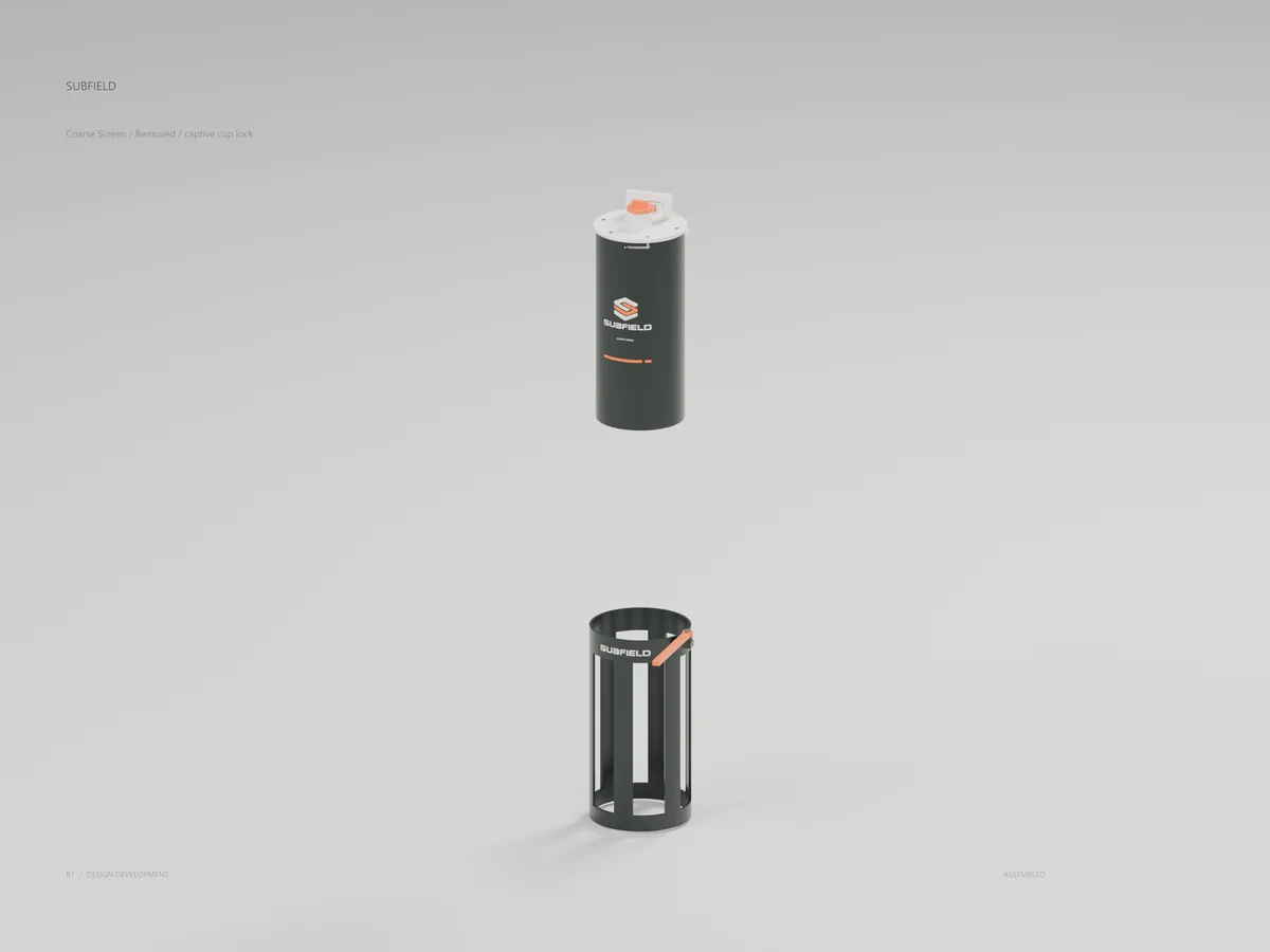
Coarse Screen
The captured assembly clears the fixed housing. Cap retention, contained cleaning, transport and safe reseating still require development.
Coarse Screen
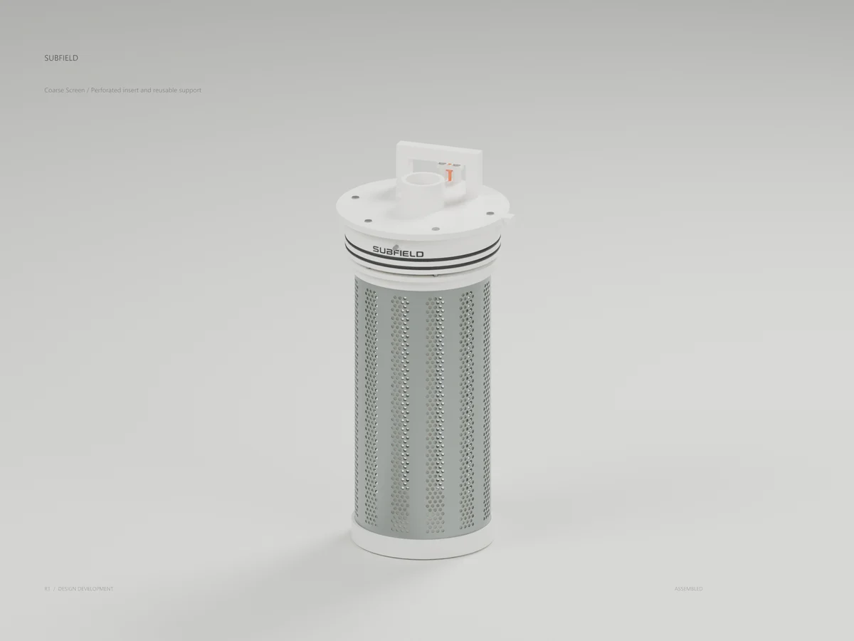
Perforated insert and reusable support
The insert contains 2,352 modeled holes aligned with twelve support windows. The 3.175 mm opening is a test candidate; the actual manufacture and hydraulic duty are unresolved.
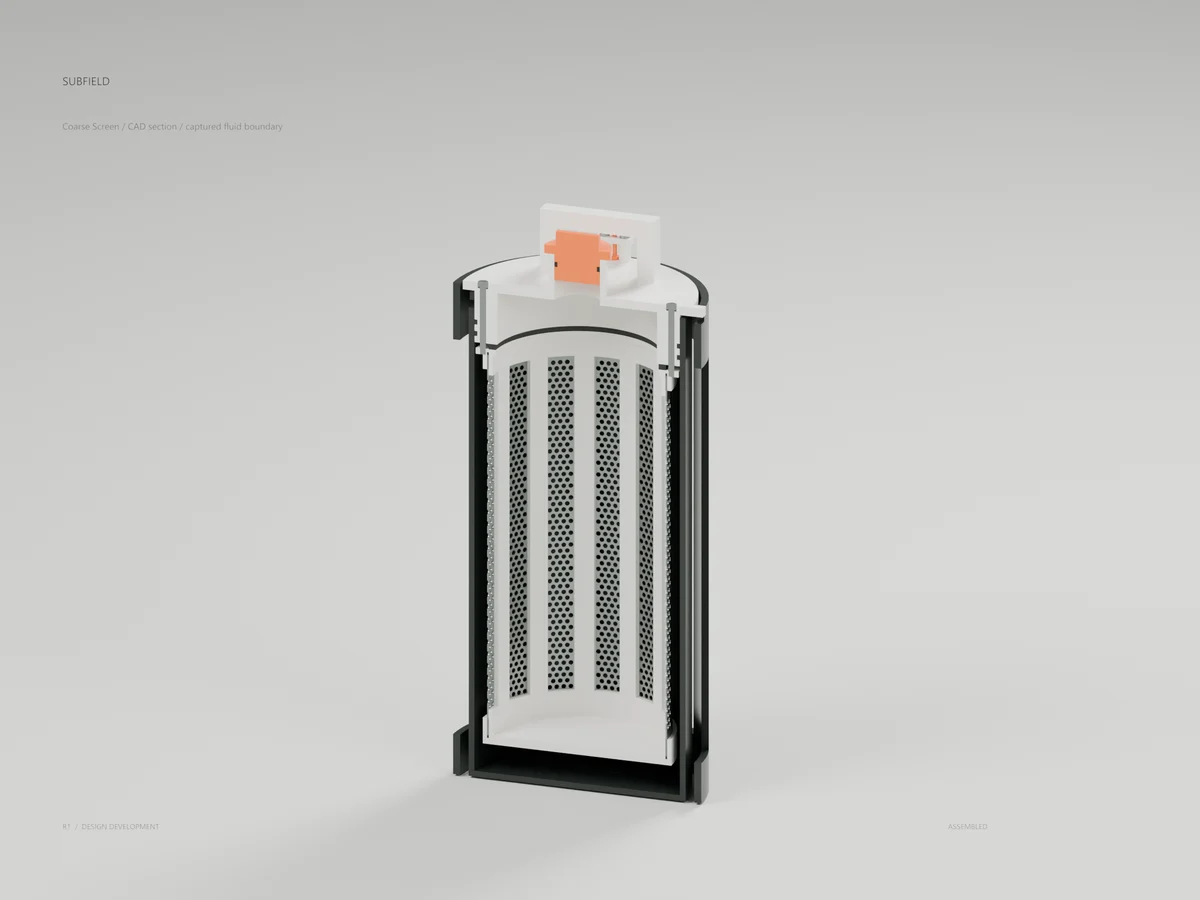
Coarse Screen
CAD section / captured fluid boundary
An actual CAD section shows the closed base, potted ends, gasketed head, cup rings and capped top bore. It does not prove leak-tight containment.
Process Integration
Service-bay detail at actual tank positions, with tank skin, framing and partitions hidden. The revised screen clears the shallow tank and three extraction lanes with 30 mm external allowance; grade actuation and primary transfer remain open.
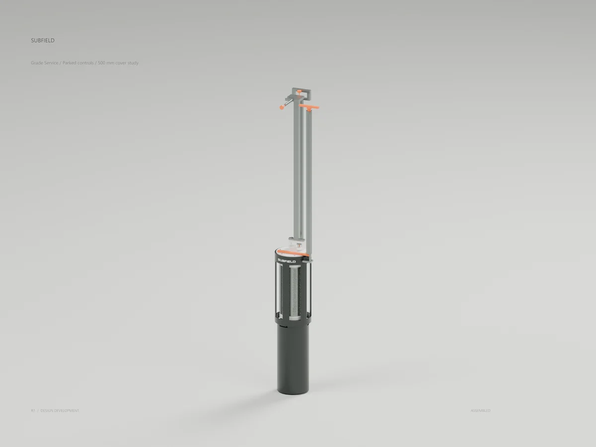
Grade Service
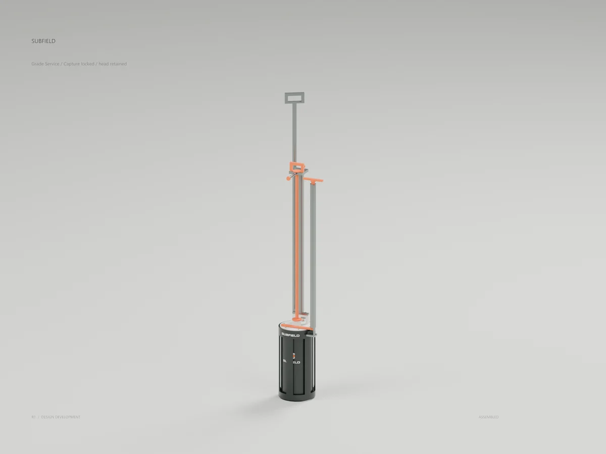
Parked controls / 500 mm cover study
Grade controls park below the existing guard at 500 mm cover. Capture mast, lock plunger, cap keeper and head retainer are separate controls; safe reach and loads remain unqualified.
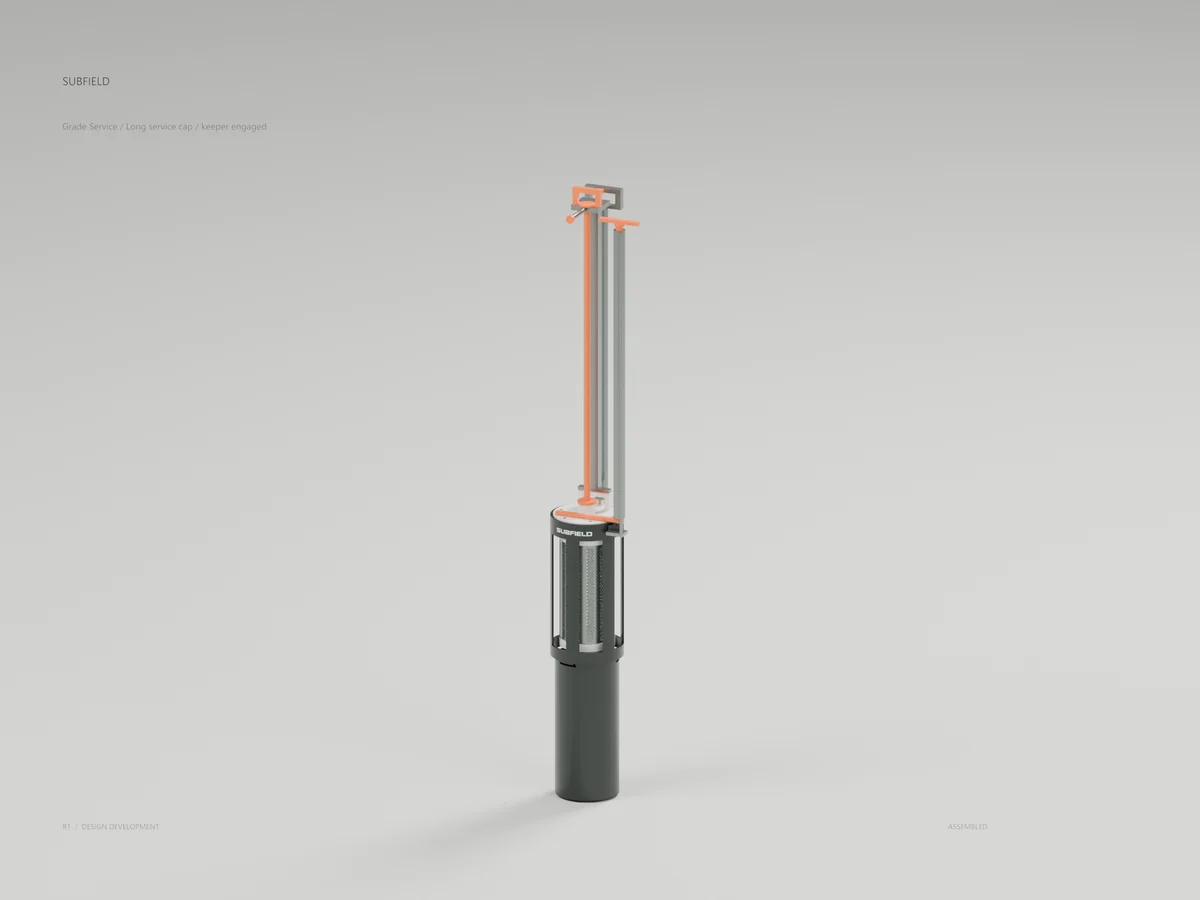
Grade Service
The long cap seats at the original outlet and is retained by a captive keeper. A side-loading guide allows its larger plug to be removed; process isolation is still required.
Grade Service
The capture mast has raised the cup and turned it 30 degrees. The captive plunger blocks reverse rotation; head release is a separate operation.
Grade Service
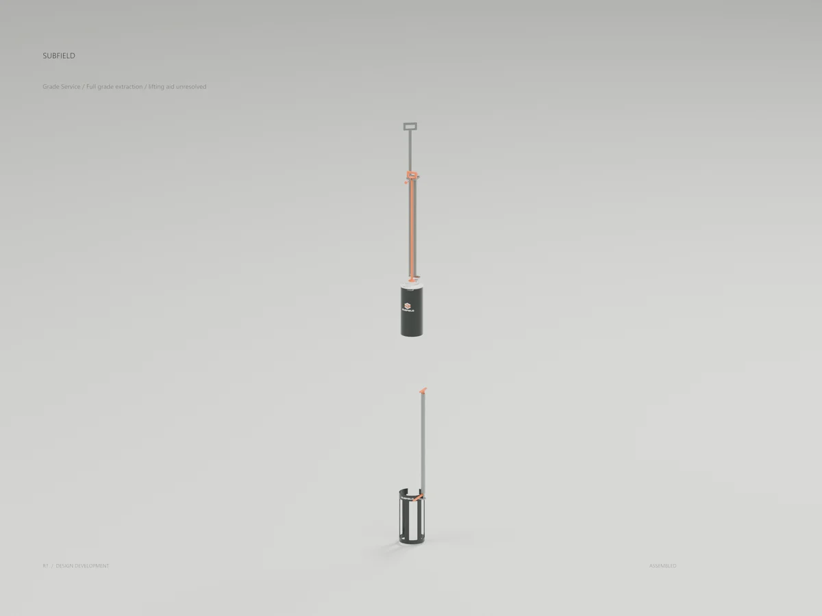
Full grade extraction / lifting aid unresolved
Full 1467 mm extraction clears the shallow opening with 30 mm external allowance. The highest grip ends 1712 mm above grade; a qualified lifting aid remains open.
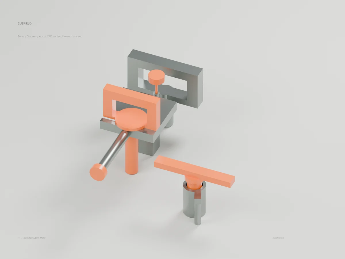
Service Controls
Actual CAD section / lower shafts cut
Actual CAD section through the upper controls, with lower shafts cut at Z1030. The model contains a guided plunger, independent retainer drive and side-loading retained cap.
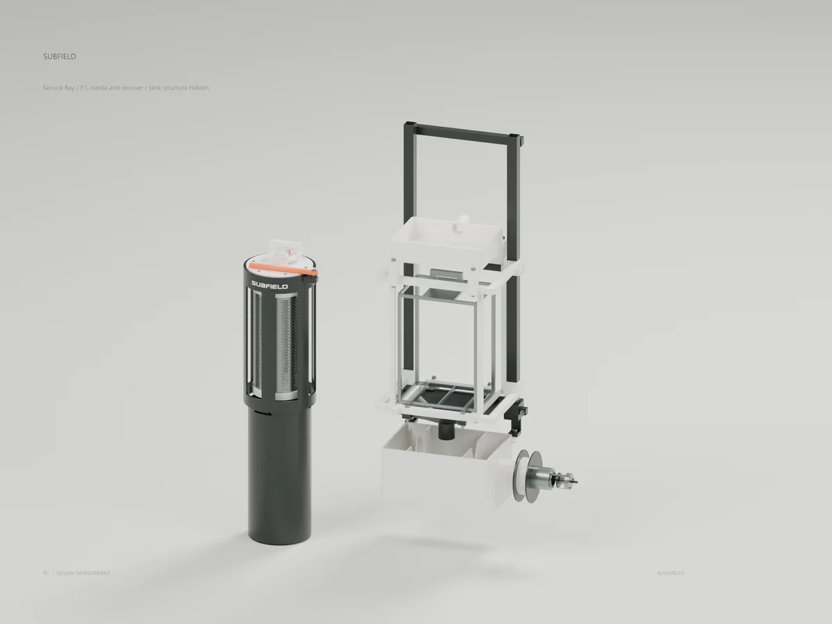
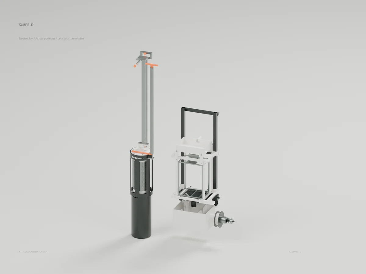
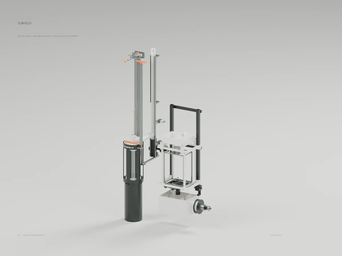
Service Bay
Actual positions / tank structure hidden
Actual screen, media and receiver positions with tank structure hidden. The grade controls clear the existing independent extraction allowances; flow connection and load qualification remain open.
Screen Transfer
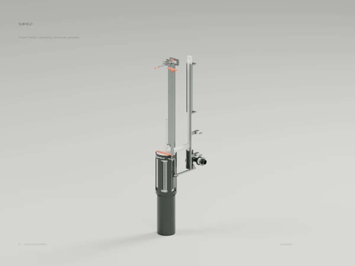
A vented F1 bridge connects to a spring-return receiver and a separate P1 sleeve. Actual CAD and service-fit checks; flow capacity, retention, loads and leakage remain unqualified.
Screen Transfer
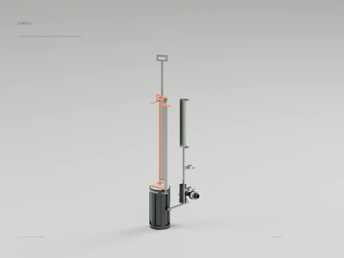
Screen Locked / preliminary geometry
The flow bridge is removed before the existing screen capture sequence. The opening upper guide returns to support the long service cap; physical service sequencing remains in development.
Vented Transfer
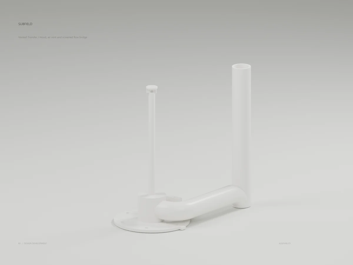
Hood, air vent and screened flow bridge
Actual CAD section showing the low hood, internal headspace vent and 32 mm screened-flow bridge. The 1522 mm crest is not a calibrated operating level.
Receiver Section
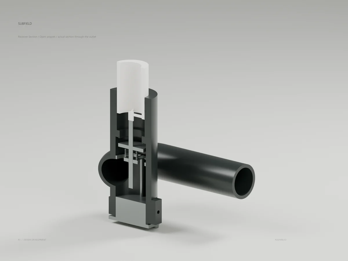
Open poppet / actual section through the outlet
A real CAD section exposes the probe, depressed poppet, spring and seat. Nominal closure precedes receiver seal exposure by 2.4 mm; physical isolation requires qualification.
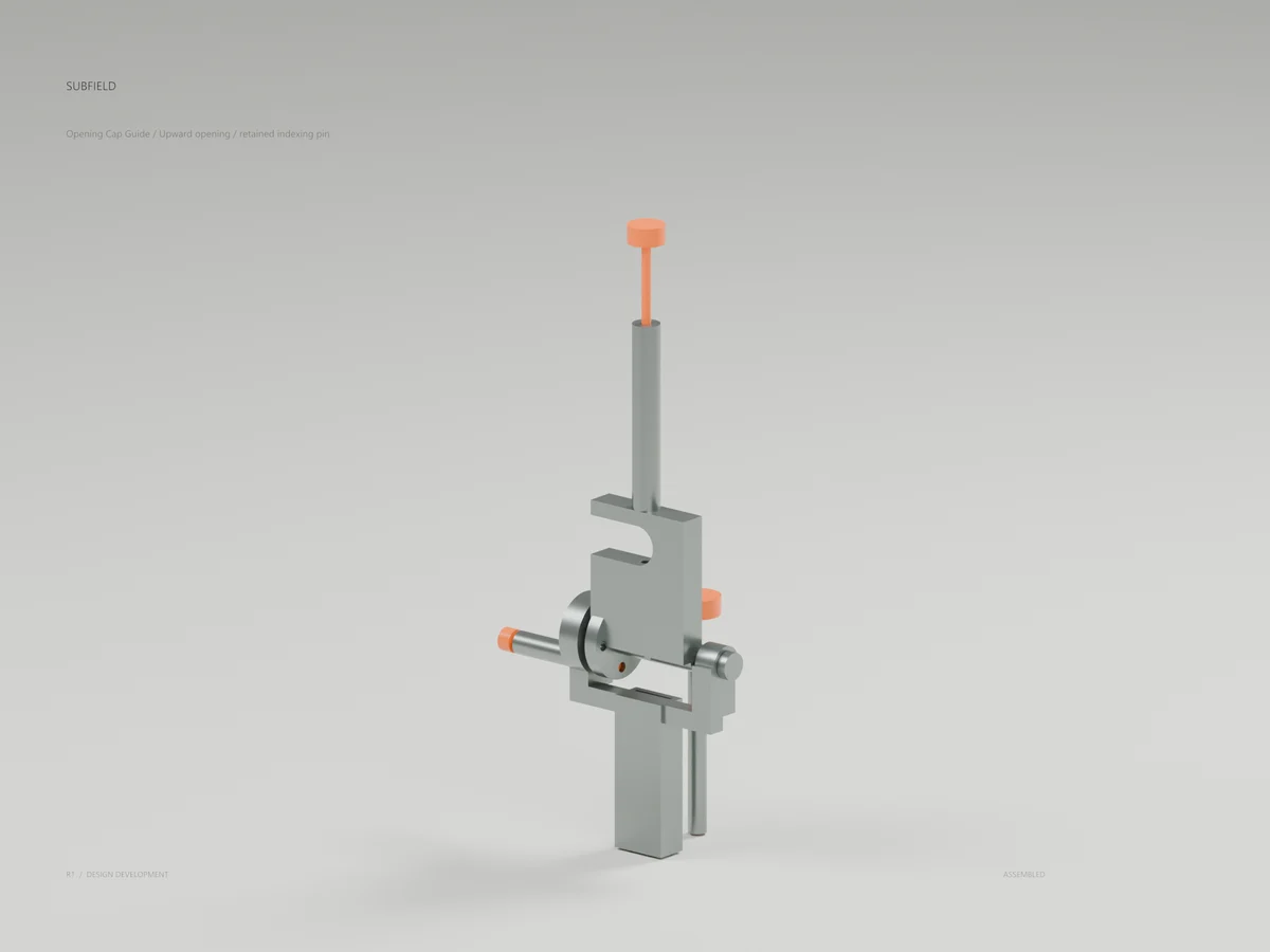
Opening Cap Guide
Upward opening / retained indexing pin
The upper cap guide opens upward and indexes in two positions. Its moving geometry clears the supporting post; the separate open-front channel passes the bridge elbow.
Service Bay
Actual positions / tank structure hidden
The screen, media and receiver retain their actual tank positions. Tank skin, partitions, roof and structural framing are hidden for inspection; the complete STEP retains them. Physical operation and service remain unqualified.
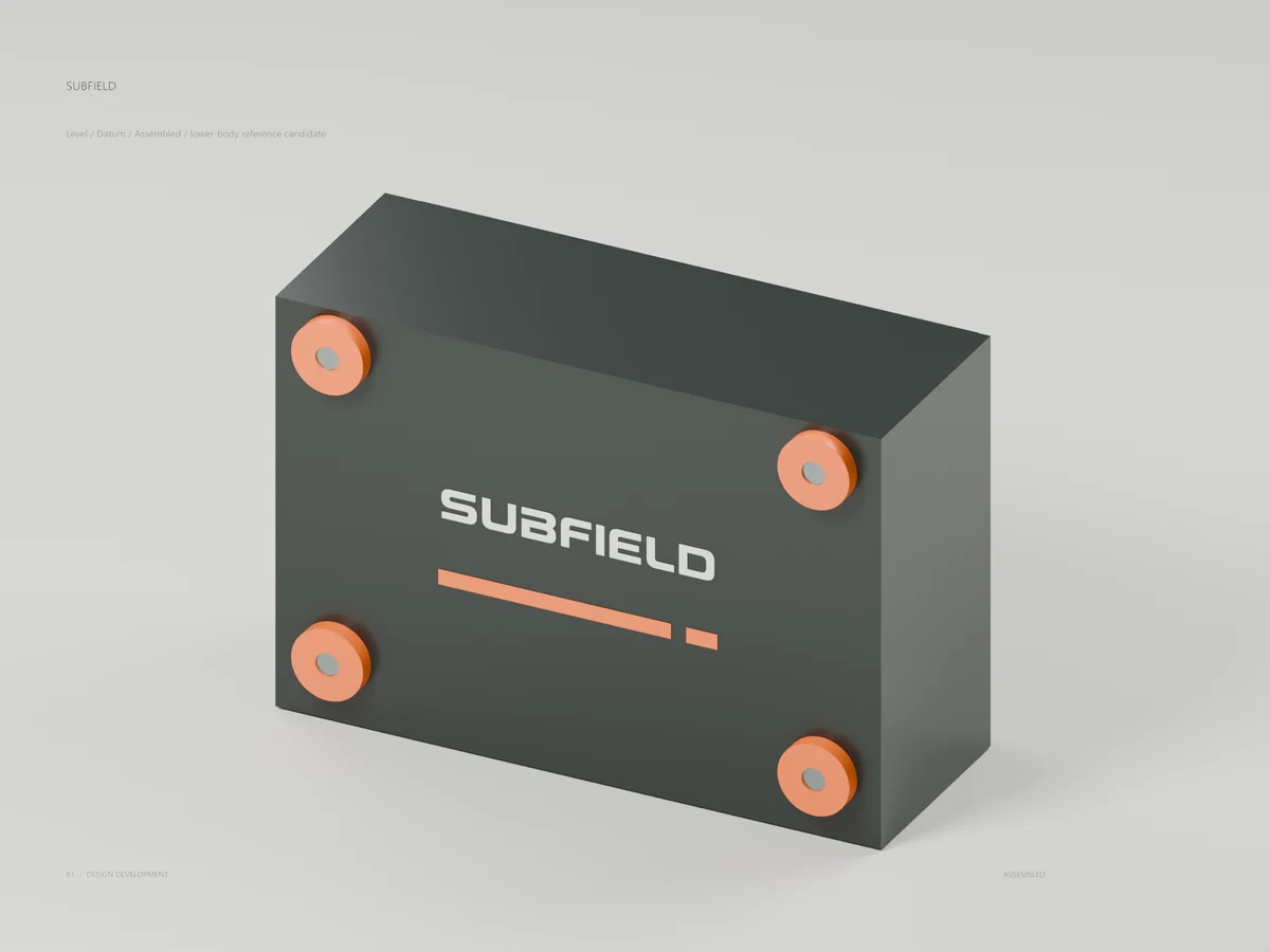
Level / Datum
Assembled / lower-body reference candidate
Protective Subfield shroud with four captive hand nuts. One of four external lower-body indicator units; no immersion or burial rating is established.
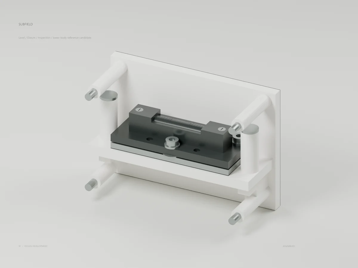
Level / Datum
Inspection / lower-body reference candidate
Authentic supplier EL80 geometry sits on a located carrier and three reference contacts. Fixed survey heads share the nominal lower-body datum; physical calibration is required.
Level / Datum
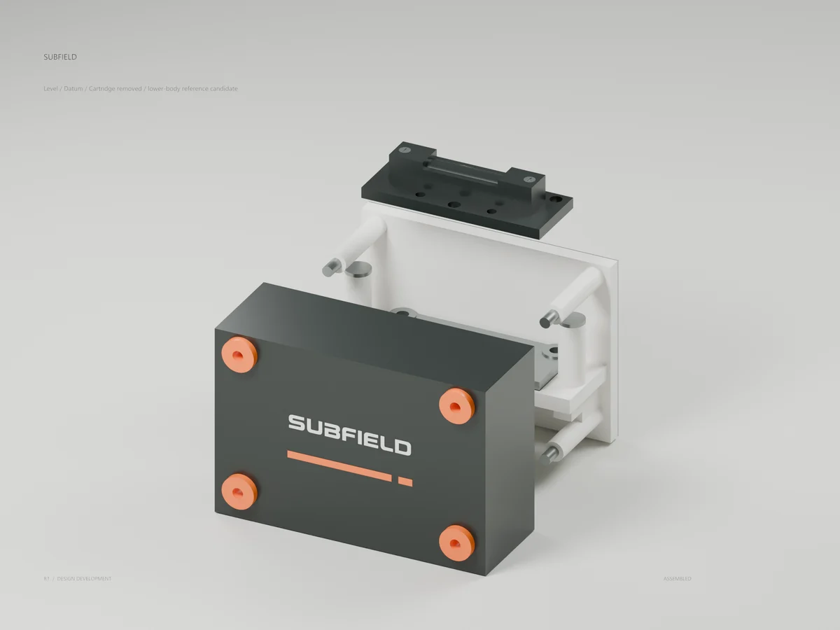
Cartridge removed / lower-body reference candidate
The carrier lifts after separate clamp removal while the reference seat stays fixed. The cover keeps its hand nuts and rings; tank sides must be exposed for this service.
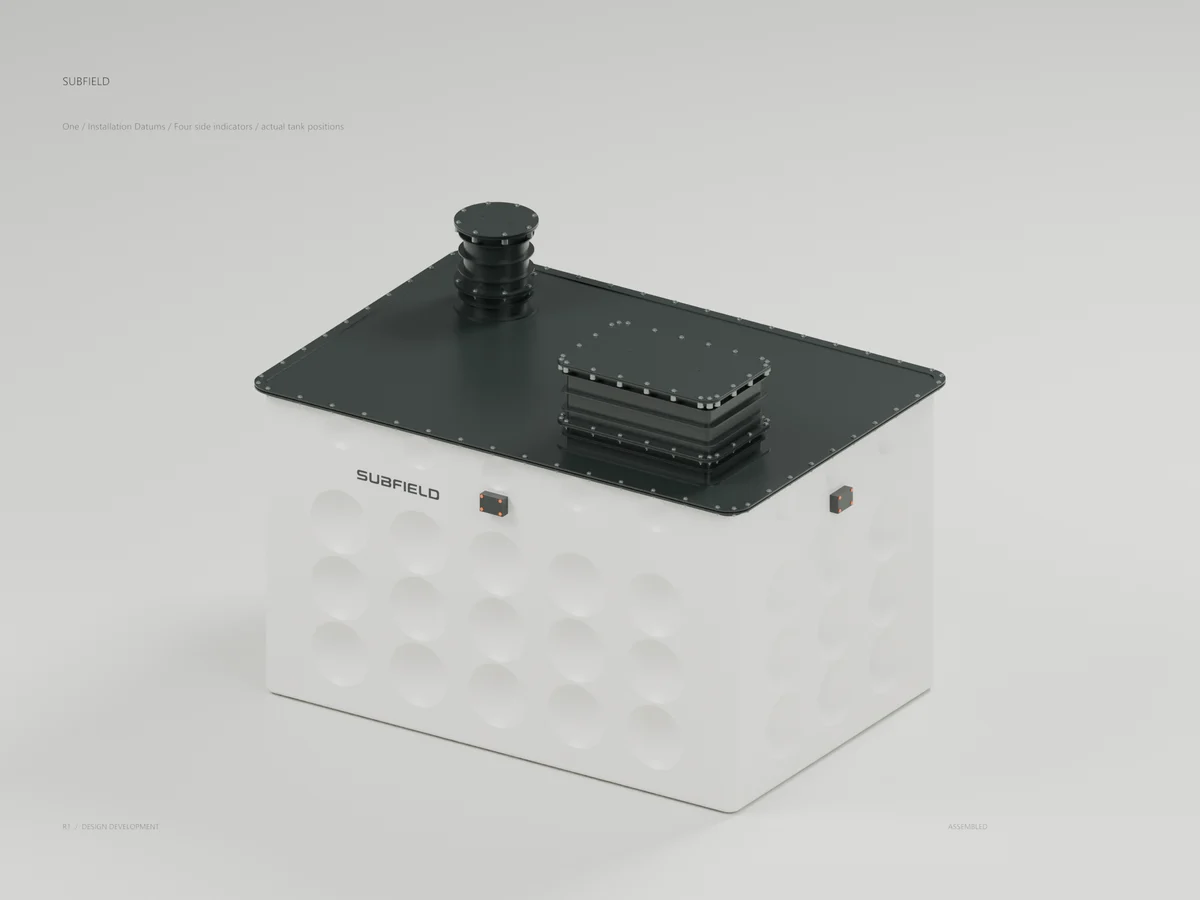
One / Installation Datums
Four side indicators / actual tank positions
All four 34-part indicators are fitted to the complete tank candidate. Eight survey heads share nominal Z1555. Local bubbles do not prove absence of distortion or settlement.
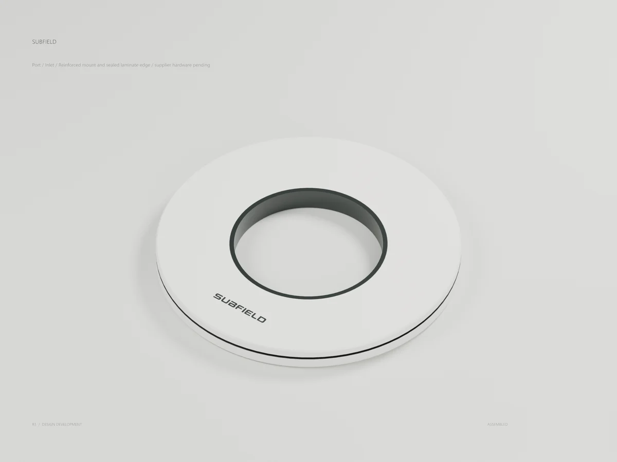
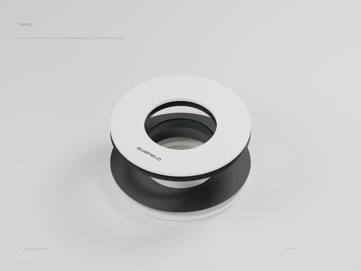
Port / Inlet
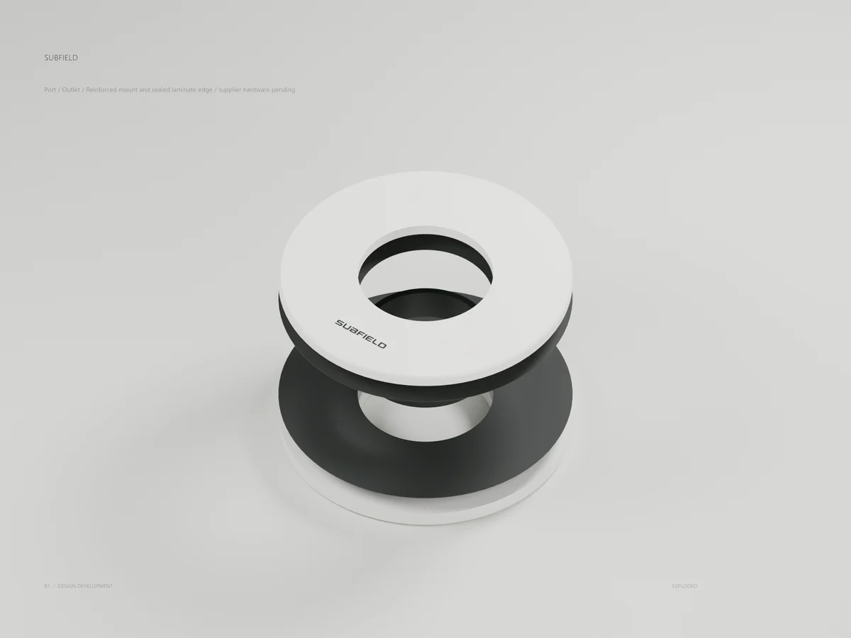
Reinforced mount and sealed laminate edge / supplier hardware pending
Original 300 mm inlet reinforcement, two face bonds and a continuous bore-edge sleeve. The proposed 4-inch supplier fitting, gasket, nut and pipe remain absent.
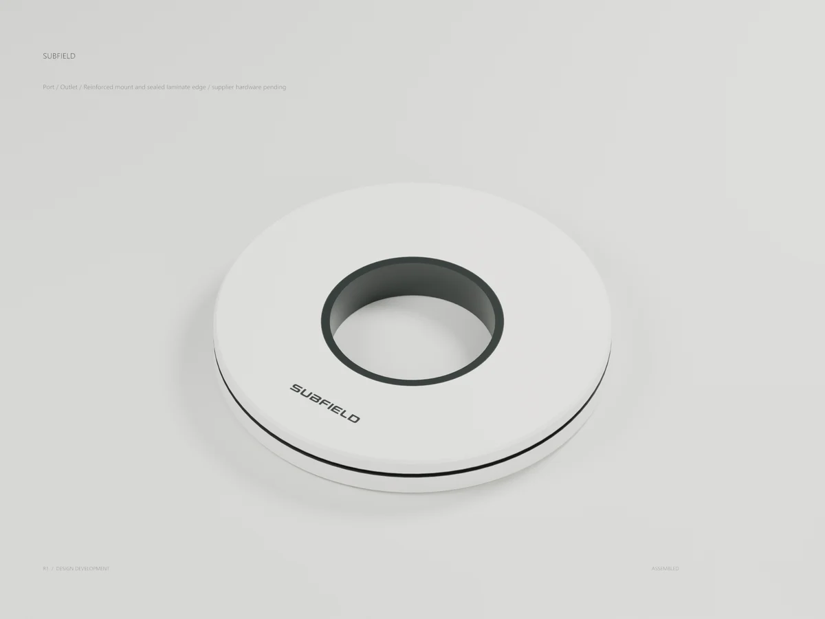
Port / Outlet
Reinforced mount and sealed laminate edge / supplier hardware pending
Original 200 mm outlet reinforcement and continuous bore-edge sleeve. The proposed 2-inch supplier fitting and complete pumped field connection remain in development.
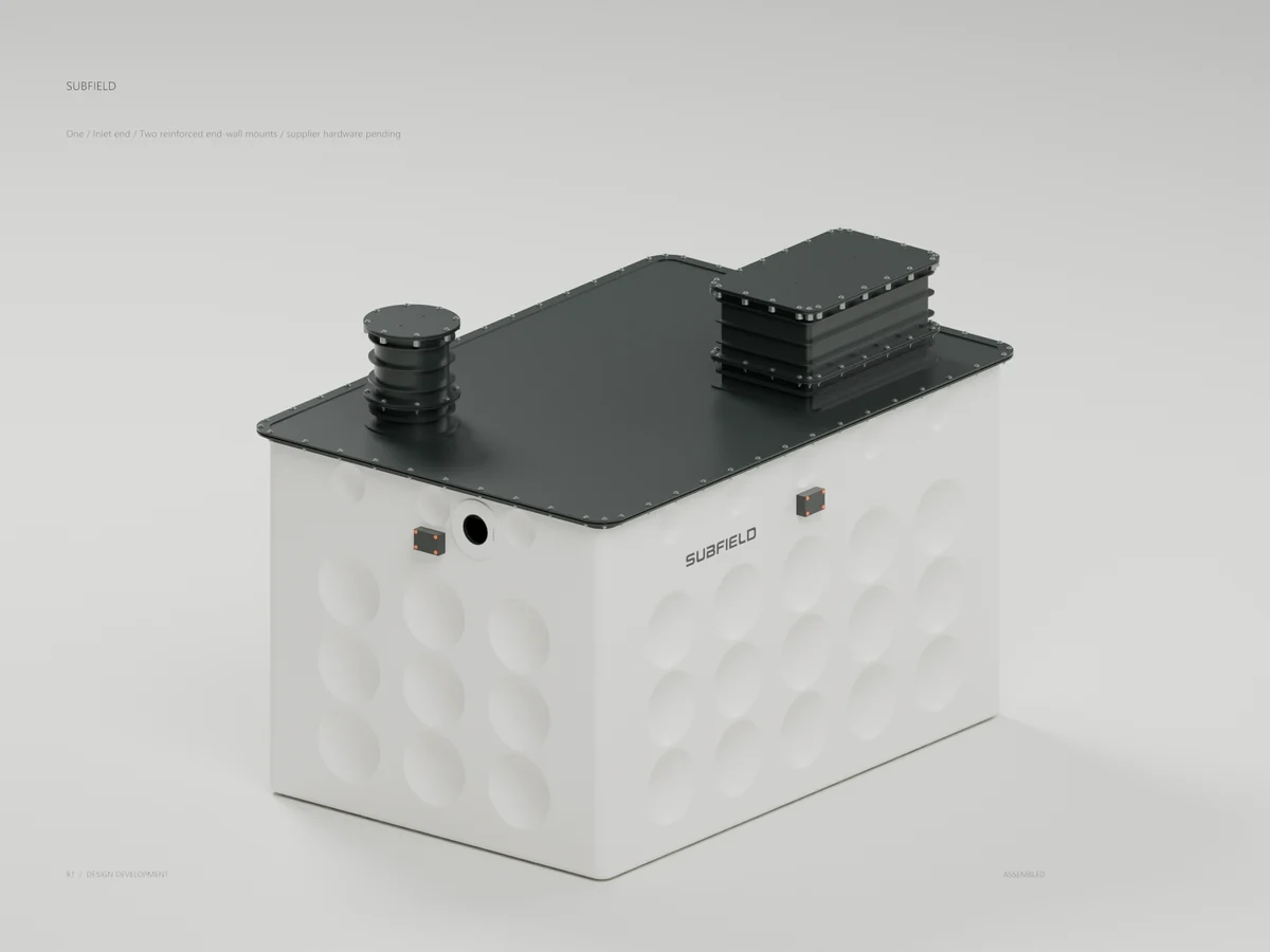
One / Inlet end
Two reinforced end-wall mounts / supplier hardware pending
Revised inlet mount is fitted to the actual end-wall cut with at least 10 mm nominal roof-rib clearance. The inlet invert is a preliminary 1585 mm allocation; hydraulics and loads remain unresolved.
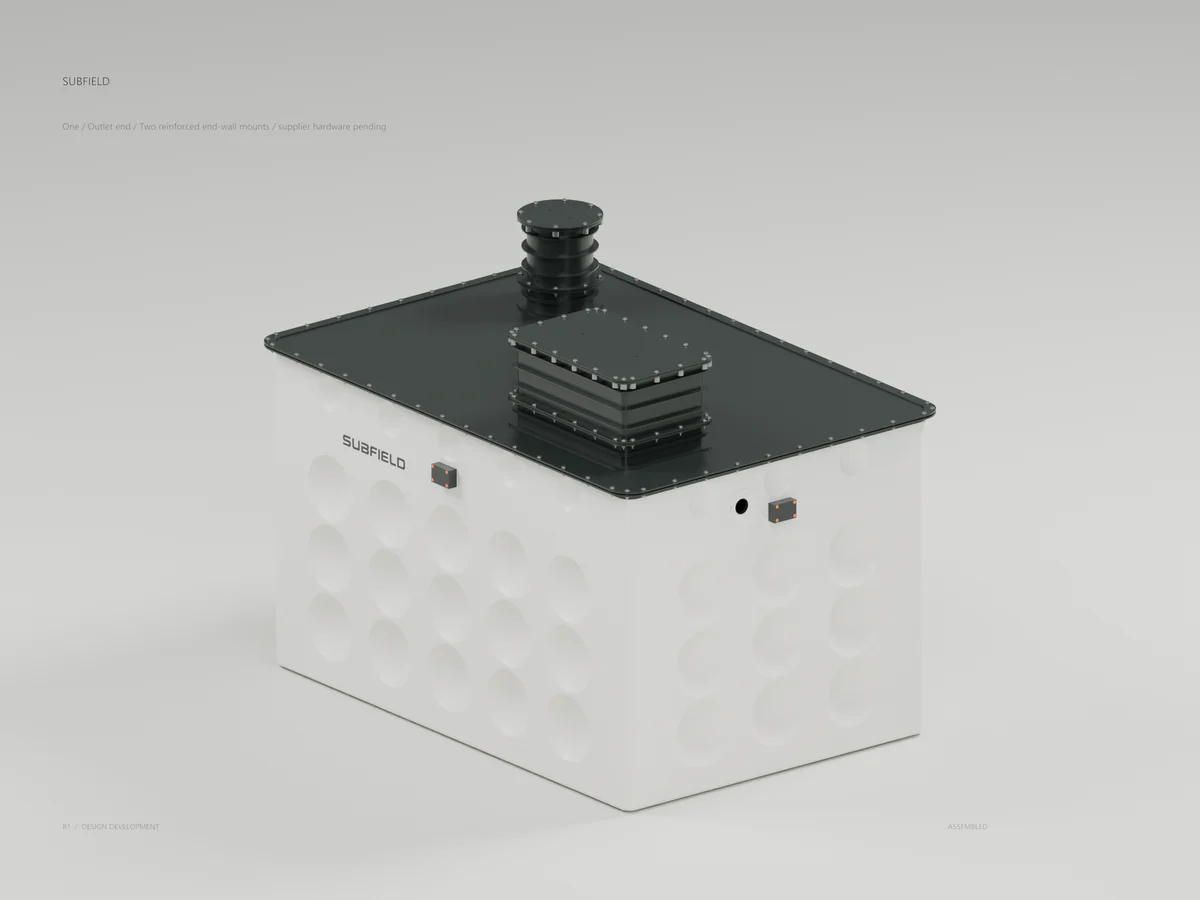
One / Outlet end
Two reinforced end-wall mounts / supplier hardware pending
The separate 2633-body tank candidate includes both original penetration mounts. Existing side-level service paths stay clear; supplier hardware, piping and physical qualification remain open.
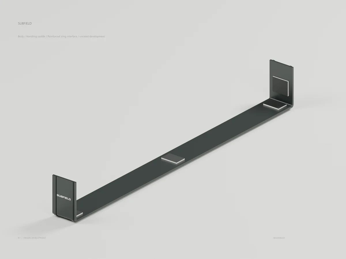
Body / Handling saddle
Reinforced sling interface / unrated development
Original continuous graphite saddle with separate lower bearing pads, side pads and nominal bond volumes. Materials, load capacity and manufacturing process remain preliminary.
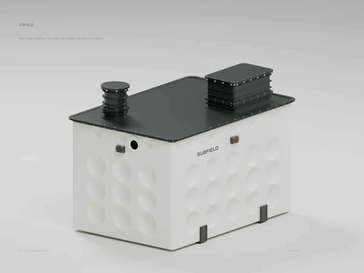
One / Body handling
Two underside saddles / unrated development
Two saddles align with permanent base crossmembers in the 2665-body tank candidate. Added assumed mass is 20.2 kg; bedding support and structural qualification remain open.
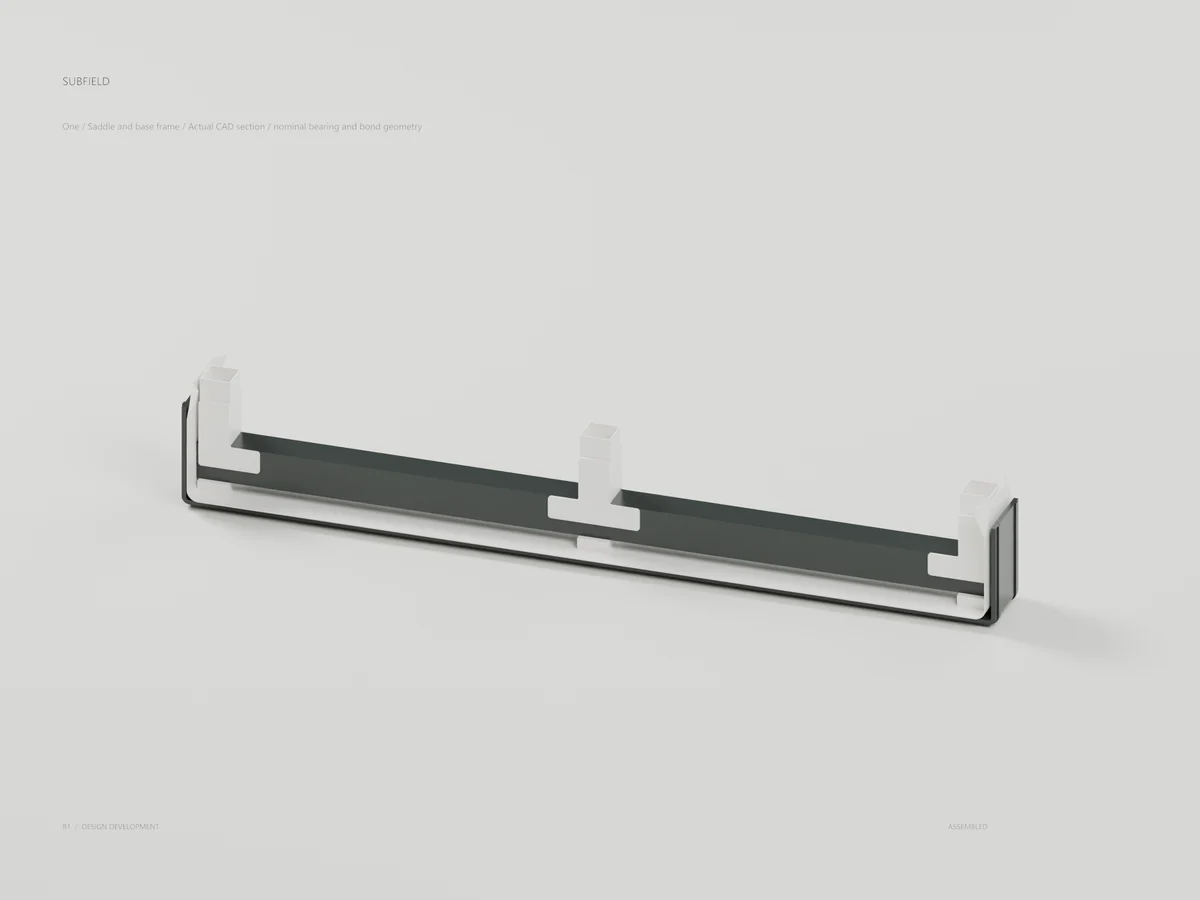
One / Saddle and base frame
Actual CAD section / nominal bearing and bond geometry
Actual CAD section through the saddle, skin, internal shoes and permanent base crossmember. Nominal contact and alignment do not establish bearing or bond strength.
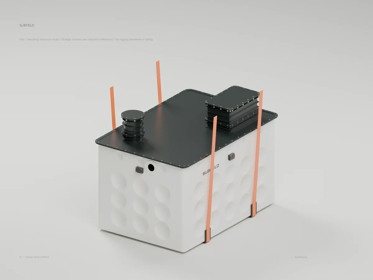
One / Handling clearance study
Orange volumes are clearance references / no rigging hardware or rating
Orange solids are clearance references, not sling or spreader hardware. Outward paths clear the tank; inward center-hook references interfere. No lifting rating or authorization is supplied.
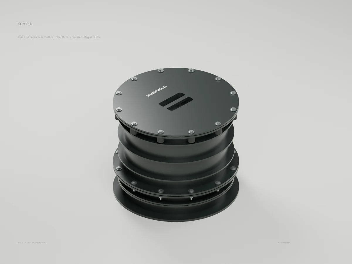
One / Primary access
520 mm clear throat / recessed integral handle
The primary throat is now 520 mm with a recessed integral cover grip, twelve captive closure stations and a separate guard. Nominal geometry; loads and usability remain unqualified.
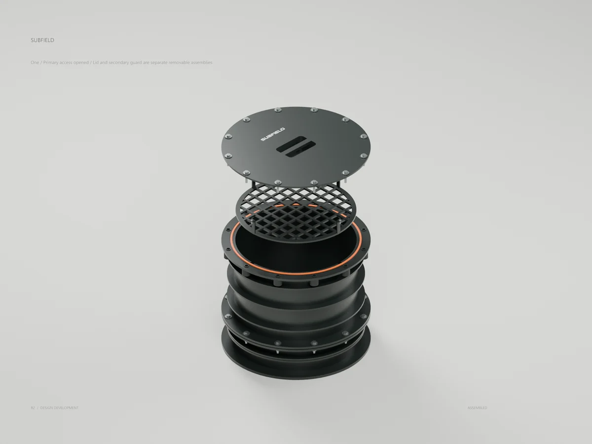
One / Primary access opened
Lid and secondary guard are separate removable assemblies
Lid and guard are separate removable groups. The fixed 520 mm throat clears the rebuilt roof; pumpout reach, inlet cleaning and full-depth access are not established.
One / Revised primary access
520 mm aperture / rebuilt roof / 500 mm cover candidate
The primary opening moves onto beam line 02. The complete candidate preserves installed equipment, supplier levels and underside saddles; manufacturing design remains in progress.
One / Permanent access frame
Actual roof B-reps / deck hidden to show trimmers and curb
Actual roof CAD with the deck hidden: two beam stubs, two headers, six T joints and an annular curb support the rebuilt ribs. The new frame needs coupled structural analysis.
Source and revision record
Source: product-render-library-r1/index-historical.html
Source SHA-256: f669d91d96807bc3c48e82ea5480a00a0ffe14d516c12fdb6363a6ced8e2cbf1
Geometry and images describe this development revision. Current product ratings and manufacturing release require separate qualification.
Keep exploring the research.
Product family / Design study
Design completion review
A request-by-request record of visual coverage and unfinished physical engineering.
Product family / Development CAD
Current product family
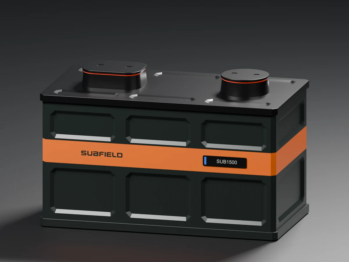
The six main product portraits from the R36 CAD presentation.
Product family / Design study
Six-product CAD gallery
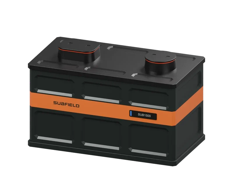
Exterior, rear, cutaway and service views for four tank models, Control and Alarm.
Return to the current product.
Explore the retrofit-only platform and its compatibility, installation and service objectives.
Explore the retrofit