Engineering records / Engineering record / MEDIA-HYDRAULICS-R1
Media Hydraulics R1.
Geometry, analysis and remaining engineering work for Media Hydraulics R1.
Retained development study. Dimensions, names and checks belong to this revision—not automatically to the retrofit-only product. Manufactured tank shells are deferred. No installation instruction, certification or manufacturing release is represented.
The source reasoning
Why this detail was investigated.
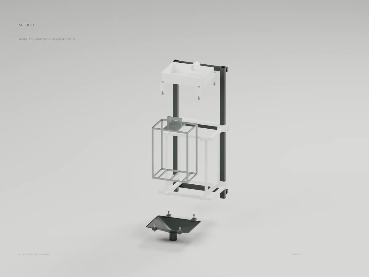
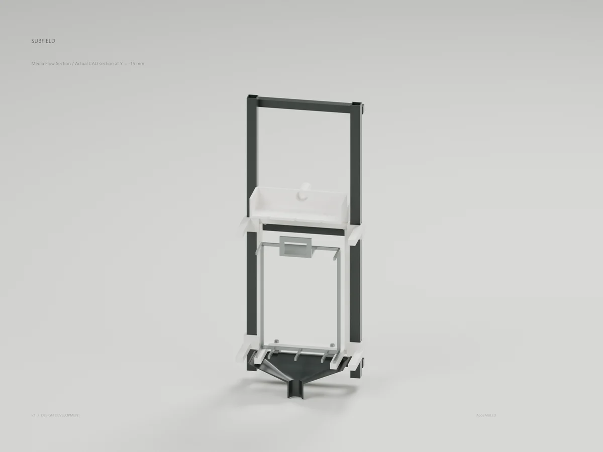
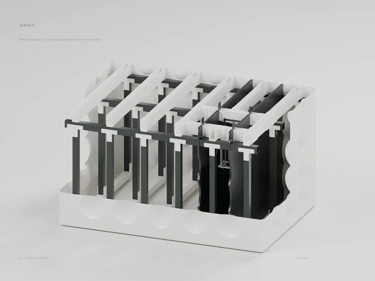
Development review of the distributor and underdrain on the existing media service carrier. The selected Subfield branding is applied to actual CAD meshes. This is CONCEPT geometry, not a manufacturing release or qualified treatment module.
Read the research and limits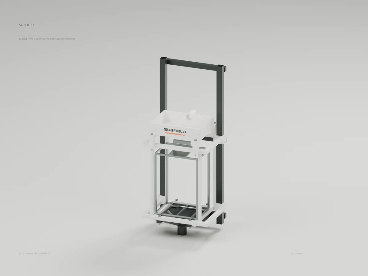

Research record
The detail behind
the study.
Source-linked work for this revision. Reported checks describe the stated model or test; physical qualification and applicability to the current retrofit remain separate.
Development review of the distributor and underdrain on the existing media service carrier. The selected Subfield branding is applied to actual CAD meshes. This is CONCEPT geometry, not a manufacturing release or qualified treatment module.
STEP units are millimetres. The assembly uses the wet-carrier local frame: X across, Y rear, Z up. Its tank transform is [830, -460, 950] mm, read from the current compartment reservation and process fit parameters. GLB/Blender geometry is converted to metres by the renderer. Studio geometry and labels are presentation only; surface artwork is not structural CAD.
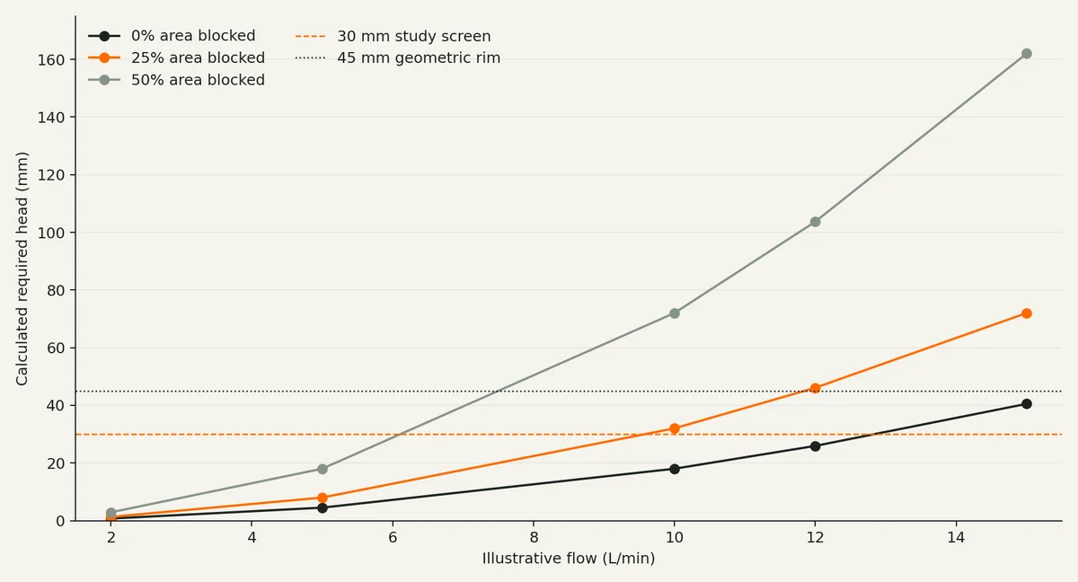
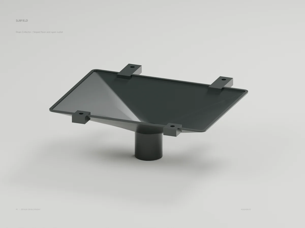
The top tray has nine 8 mm outlets and a 30 mm rear inlet bore. The collector has a lofted sloped interior and 32 mm outlet bore. They terminate at open connection planes: no supply line, isolation valve, receiver, recycle/final split or biological medium is included. The collector end at tank Z925 is only 25 mm above the EQ upper study level; this does not define backwater or an approved air gap.
Remove the whole carrier for bench service; the distributor must then be removed before cassette-only extraction. Eight fasteners use tools and are not captive. Existing short guides, tank spine mounting, hydraulic disconnections, lifting equipment and operator reach remain to be developed. The clear external sweep and sampled rigid internal motion do not prove complete no-entry service.
Materials, chemical aging, manufacturing method, finished radii, tolerances, hardware grade/torque and wet-load qualification remain open. The nominal M6 hardware envelopes omit threads. The earlier product renders and remaining system work are in the adjacent product-design-r1 and manufacturing-handoff folders of the workspace.
Render with Blender 5.2.1 using product_render.py, the new output's scene.json and this package's brand directory. Use media_render.py for the shallow collector detail; it puts camera typography in front of the ground plane. Render states assembled / exploded for the main assembly and assembled for section, distributor, collector and tank-fit. Add --python-exit-code 1 before Blender's --python flag so script failures return a failed process status. The saved render records contain exact source, scene and artwork hashes. Review scripts under work/ use workspace-relative paths and should be run in the same septic/cad, outputs and work directory layout.
Source and revision record
Source: media-hydraulics-r1/READ-ME.md
Source SHA-256: a2fd91b819cfb2e8435a197a603477c2ceae66638747c4cfd0002a606524d2c1
Geometry and images describe this development revision. Current product ratings and manufacturing release require separate qualification.
Return to the current product.
Explore the retrofit-only platform and its compatibility, installation and service objectives.
Explore the retrofit