Engineering records / Engineering record / BASE-FRAME-R1
Base Frame R1.
Geometry, analysis and remaining engineering work for Base Frame R1.
Retained development study. Dimensions, names and checks belong to this revision—not automatically to the retrofit-only product. Manufactured tank shells are deferred. No installation instruction, certification or manufacturing release is represented.
The source reasoning
Why this detail was investigated.
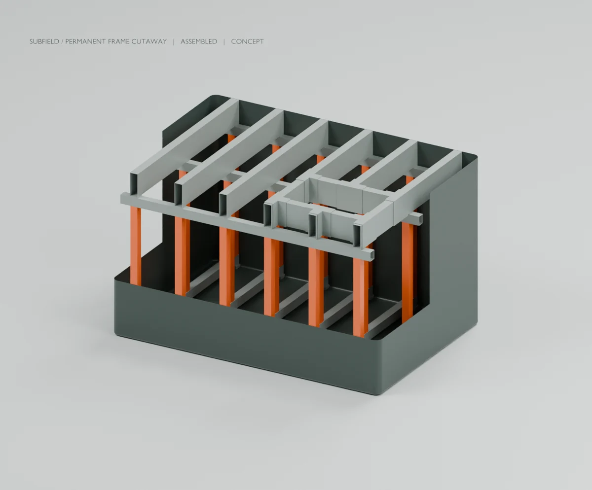
The 85-solid assembly adds six base crossmembers, 18 permanent posts and 18 shaped floor-contact shoes to the fitted vessel/roof. The intended compression sequence is roof → seats → support rails → posts → base crossmembers → shoes → floor → external bedding. Contact geometry exists; load capacity is not established.
Read the research and limitsResearch record
The detail behind
the study.
Source-linked work for this revision. Reported checks describe the stated model or test; physical qualification and applicability to the current retrofit remain separate.
Permanent support-frame candidate
The 85-solid assembly adds six base crossmembers, 18 permanent posts and 18 shaped floor-contact shoes to the fitted vessel/roof. The intended compression sequence is roof → seats → support rails → posts → base crossmembers → shoes → floor → external bedding. Contact geometry exists; load capacity is not established.
The initial post section is 80 × 80 × 3 mm with 1347 mm length; the base members are 90 × 100 × 3 mm. Shoes follow the modeled floor transition. These dimensions are original development choices, not qualified production sections. Joints, lateral bracing, uplift retention, local bearing and the floor/bedding interface are still unfinished.
At an assumed 1560 kg/m³, added base members weigh 21.61 kg, posts 34.95 kg and shoes 7.83 kg: approximately 64.38 kg total. The first support layout is therefore too costly in mass to preserve the old weight allocation without redesign elsewhere. No completed-tank weight is asserted.
The STEP preserves the full skin and all separate solids. The Blender scene cuts away part of the skin for inspection only. Neither the cutaway nor nominal contact demonstrates a structurally continuous or qualified connection. Tube-end treatment and whether cavities can flood must be resolved for cleaning, durability and displacement accounting.
199 geometry/export checks pass. These inspect individual solids, skin clearance, nominal support contacts, upper-assembly interference and STEP solid preservation. They do not establish stiffness, compression capacity, joint strength, buckling resistance, floor punching or environmental performance.
Source and revision record
Source: base-frame-r1/READ-ME.md
Source SHA-256: c7cdd6f557c0802099d848bd632c452fe10b2080b27aa7dd6c7a725234b8568d
Geometry and images describe this development revision. Current product ratings and manufacturing release require separate qualification.
Return to the current product.
Explore the retrofit-only platform and its compatibility, installation and service objectives.
Explore the retrofit