Engineering records / Engineering record / ACCESS-RISERS-R1
Access Risers R1.
Geometry, analysis and remaining engineering work for Access Risers R1.
Retained development study. Dimensions, names and checks belong to this revision—not automatically to the retrofit-only product. Manufactured tank shells are deferred. No installation instruction, certification or manufacturing release is represented.
The source reasoning
Why this detail was investigated.
Development geometry for the current 2000-gallon tank study. The complete system is not ready for manufacture.
Read the research and limits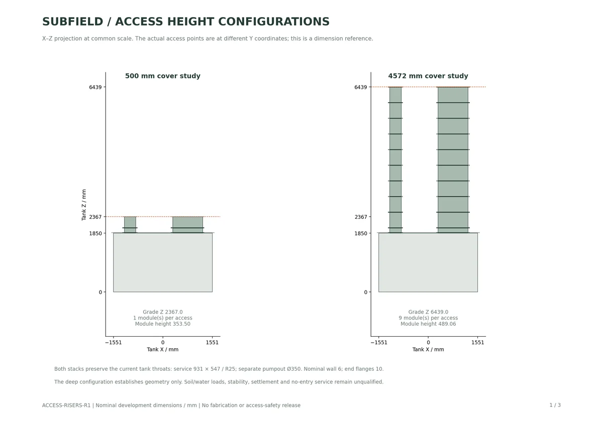

Research record
The detail behind
the study.
Source-linked work for this revision. Reported checks describe the stated model or test; physical qualification and applicability to the current retrofit remain separate.
Development geometry for the current 2000-gallon tank study. The complete system is not ready for manufacture.
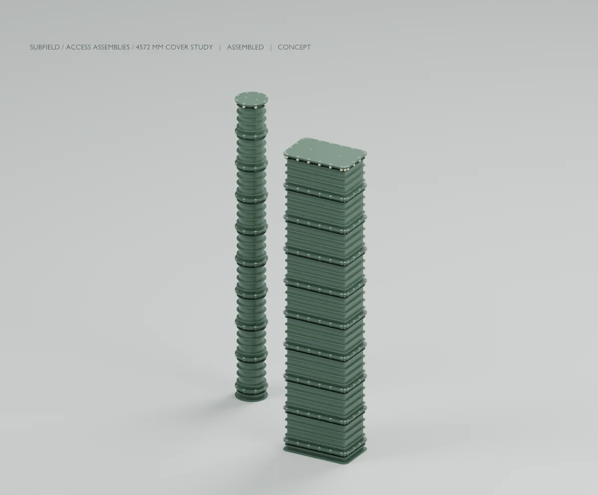
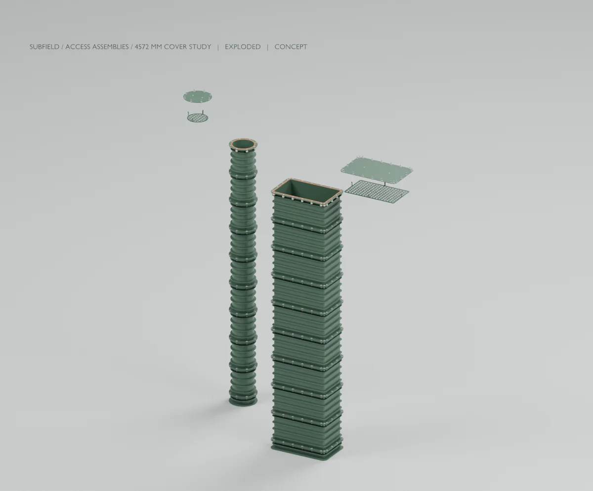
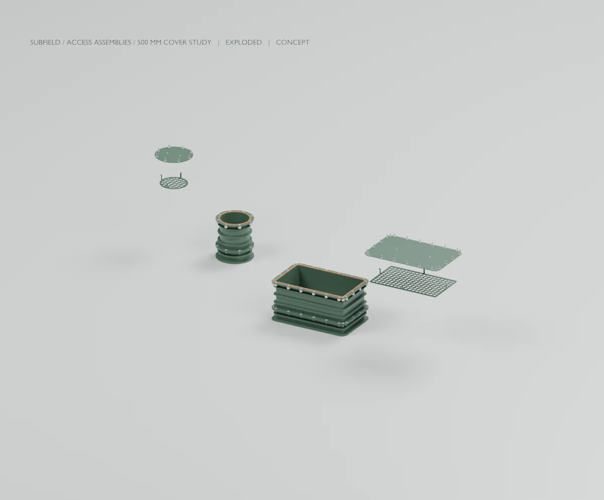
Both configurations preserve the 931 × 547 mm / R25 service throat and the separate Ø350 mm pumpout throat. Each has a bonded base adapter, flanged riser modules, a secured removable cover, an independently fastened secondary grate and explicit seals/hardware. These are provisional custom fabrication interfaces; they are not proprietary supplier CAD or qualified off-the-shelf risers.
| Case | Modules per opening | Module height | Combined solids | Geometry/interface checks | Incomplete installed mass |
|---|---|---|---|---|---|
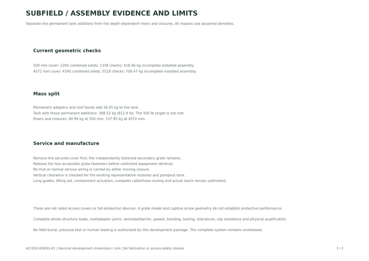
| 500 mm cover | 1 | 353.50 mm | 2260 | 1358 | 418.46 kg |
| 4572 mm cover | 9 | 489.06 mm | 4340 | 5518 | 706.47 kg |
Cover is measured from the existing flange reference at Z1867. Study grade is Z2367 or Z6439. Cover plate top is 11 mm above its study grade and the nominal closure screw head reaches 20.9 mm above grade. No permitted burial depth or traffic/pedestrian/fall-protection rating is established.
Each cover-...mm folder includes the complete vessel-with-access.step, access-only access-assemblies.step, custom base adapters, first riser module, upper module with guard mounts, covers and secondary grates. All STEP dimensions are millimetres. The upper module is a distinct variant; its blind guard-mount bosses and pockets must not be omitted.
The folders also contain the generated part takeoff, geometry and motion reports, CAD-driven Blender/GLB scenes and assembled/exploded images. The 500 mm closure detail is an actual STEP cutout through one captive fastener. Its tank-overview folder shows the formed vessel, roof/perimeter joint and access assemblies together, extracted directly from the combined STEP. Internal frame members and roof ribs are hidden in that exterior presentation and remain in the complete STEP. Exploded states are inspection arrangements, not a certified handling or lifting procedure.
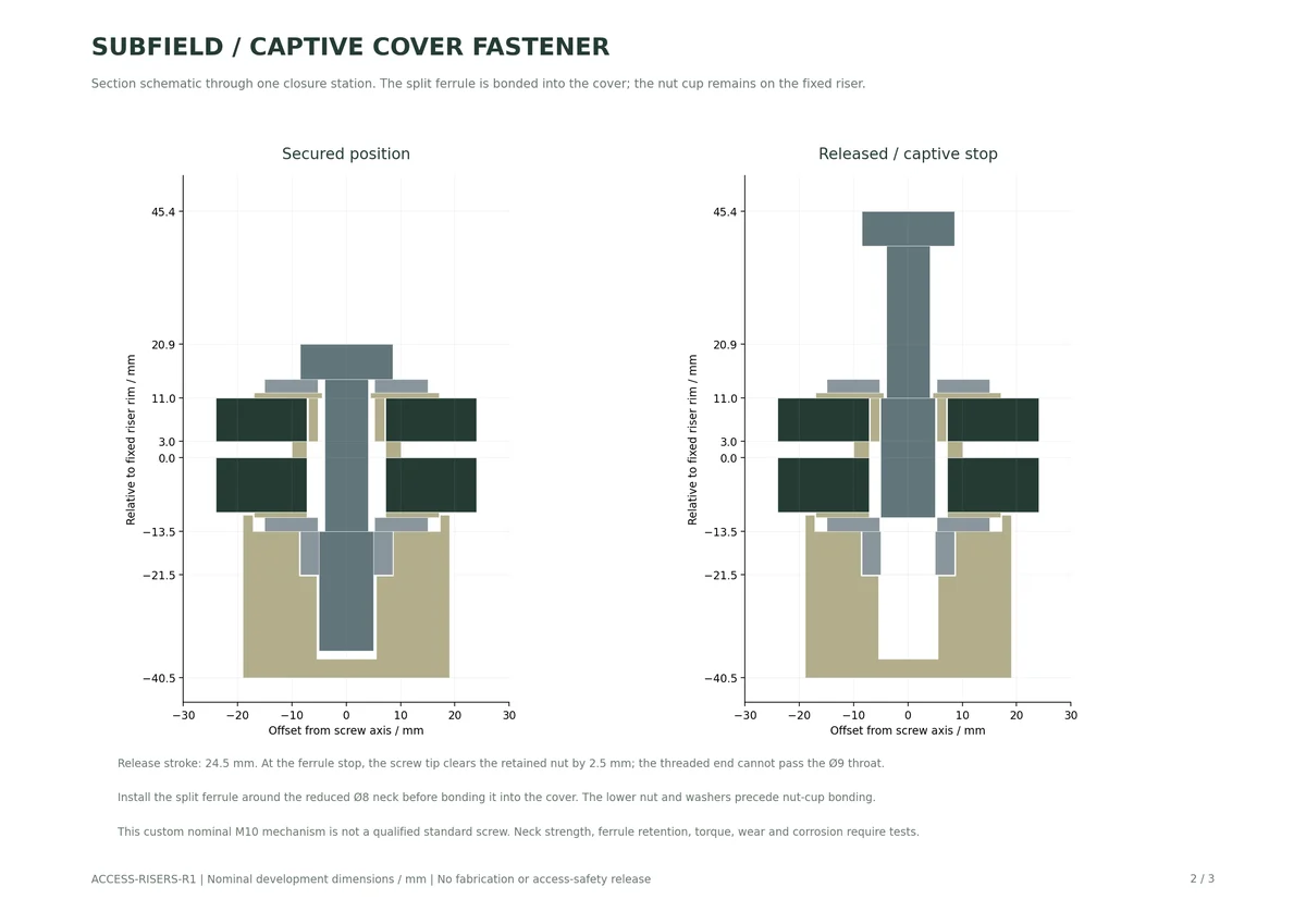
access-assembly-review.pdf provides three reference sheets covering depth configurations, captive screw geometry and assembly/mass implications. current-cad-source.zip contains editable source, parameters, tests and pinned dependencies. controlled-input/ contains the exact previous tank STEP and supporting report/manifest needed to reproduce this revision. artifact-sha256.json checks the package files.
The cover has a ribbed underside and two blind nominal M10 lifting-tool ports with plugs. Neither those ports nor the unfinished lifting tool has a working load limit. The primary seal is separate from the secondary grate, whose four M6 fasteners are accessible at the rim. All normal Hub and process wiring remains on future fixed supports; none is attached to either moving closure.
The cover screws have a nominal M10 threaded end, a reduced Ø8 neck and a split insulating ferrule. The ferrule is assembled around the neck and bonded into the cover; its Ø9 retaining throat captures the larger threaded end. Nominal screw release is 24.5 mm, leaving 2.5 mm clearance above the retained nut at the capture stop. Nuts and lower bearing washers are installed before their separate retaining cups are bonded beneath the fixed flange. These custom geometric details have not been qualified for strength, wear, thread locking, torque retention or corrosion.
Riser joints use 10 mm flanges, 3 mm discrete compression stops and equal-volume gasket envelopes derived from a 6 × 4 mm free section. The riser walls are nominally 6 mm with external stiffening bands. These are geometric choices, not a production laminate or proof of stability under soil and groundwater.
The full CAD suite passed 97 tests in 59.84 seconds. Both assembly generators passed their geometry/contact/service and STEP reimport checks, and both independent captive-screw checks passed. The motion check samples three axial positions and verifies deliberate interference at 0.2 mm overtravel into the ferrule shoulder; it does not model threads, operator actions, tolerances or service life. The drawings and rendered views were inspected before packaging. No physical loading, leak testing, human reach study or fabrication trial was performed.
Permanent adapters and roof bonds add 16.45 kg. The tank with these additions is 368.52 kg (812.4 lb), above the approximately 500 lb target. The remaining 49.94 kg / 337.95 kg belongs to the shallow/deep risers and closures. All figures use assumed densities; the remaining product components add further mass.
Close the combined roof/adapter/riser load path, external pressure and stability, settlement and pullout, dead loads, uplift, repeated service, leakage and environmental aging. Resolve material/laminate/barrier, adhesives, gaskets, surface finish and slip resistance, captive hardware and lifting tools. Complete mold splits/radii, tolerances, bond preparation, process controls and inspection. The drawings are nominal interface references, not released manufacturing drawings.
The secondary grates are unqualified geometric candidates for an independent protection layer. Do not treat them as rated fall protection. Covers and grates require their own retention, impact, load and service evidence. The full bore and representative equipment sweeps are clear only after the appropriate closures are removed; complete safe servicing still needs the long guides, lifting aid, containment actuation, connector parking, Hub carrier, routed services and demonstrated no-entry reach.
The remaining process components, controls and electrical packaging, tank load qualification, 1500/3000-gallon variants and complete manufacturing release remain in the adjacent central handoff. This access package does not complete those scopes.
Extract current-cad-source.zip into this folder. From its cad directory:
Render each generated scene through wet_render.py into a separate views folder. The deep configuration and tank overview use access_render.py, which reuses those CAD meshes and reserves caption space around the projected assembly bounds. Blender 5.2.1 LTS produced these views. The reference drawing script accepts --out pointing at the rebuilt access root and requires Matplotlib. The upstream STEP is hash-pinned; re-exporting it is a new input snapshot and requires a deliberate verified revision.
The service-mechanics brief governs independent closures, stationary Hub support and no-entry retrieval. The riser scope and secured access scope retain qualification requirements. Orenco's FRP risers and Polylok's secondary screens are reference mechanisms, not selected components or ratings transferred to this custom geometry.
Source and revision record
Source: access-risers-r1/READ-ME.md
Source SHA-256: 54d5c56a05f849d927fbb0a0fcb9e28c7a3cb47e32b9b92d79d982478f2448ad
Geometry and images describe this development revision. Current product ratings and manufacturing release require separate qualification.
Return to the current product.
Explore the retrofit-only platform and its compatibility, installation and service objectives.
Explore the retrofit