Connections / Design study / SUBFIELD-CABLE-R1
A substantial connection.
The cable, conductors, keyed connector and strain relief developed as one system.
Retained development study. Dimensions, names and checks belong to this revision—not automatically to the retrofit-only product. Manufactured tank shells are deferred. No installation instruction, certification or manufacturing release is represented.
The source reasoning
Why this detail was investigated.
A smooth outer jacket and a progressive transition bring handling, identification and service into the same design study.
Read the research and limits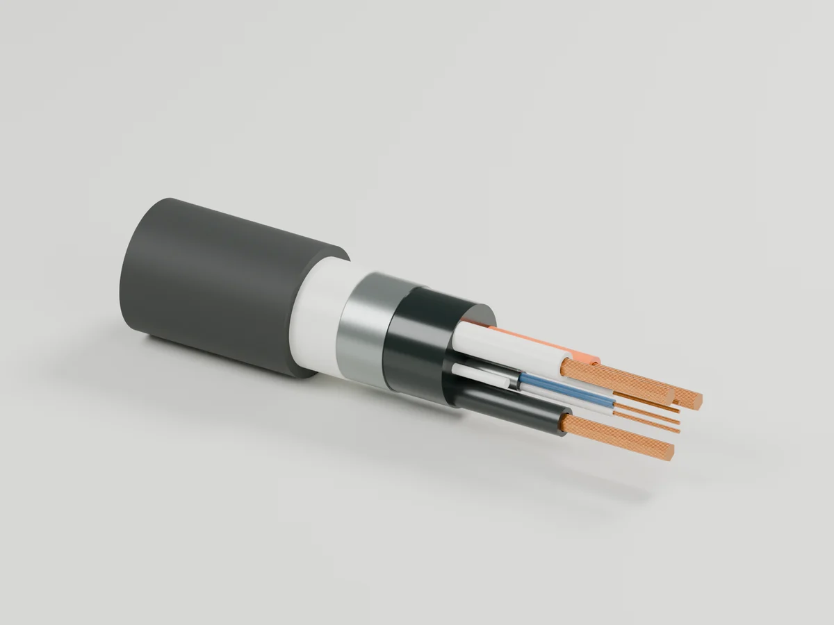
The cable cross-section.
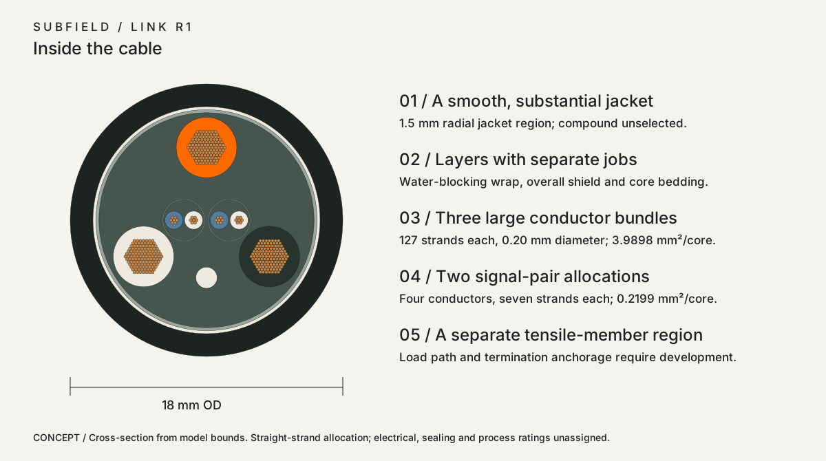 Open the full-size review drawing
Research record
The detail behind
the study.
Source-linked work for this revision. Reported checks describe the stated model or test; physical qualification and applicability to the current retrofit remain separate.
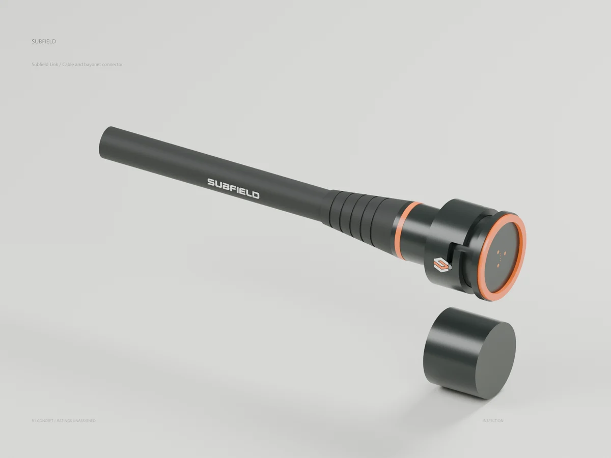
A smooth graphite cable. A long, flexible transition. An orange signature. The cable, conductors and connector developed as one Subfield product.
Build the feel from the inside.
The first construction allocates three large cores and two signal pairs, with separate shielding, water-blocking and tensile regions. This is a representative sample of the intended trunk, with electrical roles still to be selected.
Seven contact positions. Deliberate engagement.
Recessed sockets, a master key and a separate class key establish the interface layout. The class-key check rejects three alternative orientations before nominal contact engagement. A bayonet collar surrounds the keyed housing.
The geometry generation passes 963 checks. Four focused regression tests pass. Both STEP files reimport as valid separate solids. Native Blender renders preserve the source vertices within 0.001 mm. The complete repository test run is tracked separately in verification-status.json.
Research result
The reference is LTT TrueSpec . LTT lists a silicone jacket, flexible TPE connector housing, copper conductors with shielding, progressive strain relief and visible capability markings. Its USB-C page offers different data capabilities at different lengths. The reviewed page does not publish an immersion/IP rating or a cable diameter, so neither is transferred to Subfield. Source: LTT official product page .
The useful design lessons are the substantial hand feel, flexible transition at the connector, readable identification and honest end-to-end performance. Our product needs its own cable construction and connector rather than a USB adaptation.
What changes for Subfield
| Reference principle | Subfield adaptation | Evidence still required |
|---|---|---|
| Flexible, substantial cable | Smooth graphite jacket; 18 mm outside diameter in this first trunk study; long tapered relief with graded flex grooves | Actual compound hardness, cold flexibility, handling force, bend radius, kink and flex life |
| Protected conductors | Separate large conductor cores, shielded signal-pair envelopes and overall shield envelope | Native electrical architecture, insulation, pair twist/impedance, shield termination and EMC |
| Clear capability markings | Subfield identity, connector class, length, serial/revision and eventually only tested ratings | Label durability, traceability and actual cable-system ratings |
| Durable termination | Separate grip collar, jacket gland, internal sealing barrier and strain relief | Pull/torque, cyclic bend, material bonding, retention, contamination and replacement trials |
A cable can be thick and flexible yet unsuitable for submerged service. Industrial PUR compounds are worth evaluating for notch/abrasion resistance and flexibility; igus publishes a specific PUR hybrid-cable example with hydrolysis and microbe resistance. That is evidence for a material-development direction, not approval of our compound or wastewater exposure. Compare actual PUR/TPE compounds and a silicone control sample before selecting the jacket. Sources: igus jacket materials , igus hybrid cable example .
Use a smooth, cleanable outer surface around the tank. An exposed textile braid would add dirt-retaining texture and would not itself provide a liquid barrier. This is a Subfield design choice, not a criticism or description of LTT construction. Avoid decorative metal armor: tensile retention should have a defined mechanical load path inside the termination.
Cable construction modeled
The representative cable is 18 mm OD with a 1.5 mm jacket region. Inside it, the CAD separates a water-blocking wrap envelope, overall shield envelope, bedding, three large insulated conductor bundles, two shielded signal-pair envelopes and a separate tensile-member envelope.
Each large core contains 127 individually modeled 0.20 mm diameter strands, giving 3.9898 mm2 of nominal copper area. Each signal conductor has seven such strands, giving 0.2199 mm2. Four signal conductors form the two pair allocations. There are 409 individual copper strands in the model. These areas are geometry choices, not ampacity ratings or a frozen wire specification. The third large core is unassigned; it is not automatically protective earth. Core colors are explanatory and do not establish a wiring convention.
The stripped construction view exposes each layer at a different length. Straight strands and straight pair positions explain the cross-section. Production strand lay, pair twist pitches, braid/foil construction, drain strategy, insulation compound, fill and extrusion are not represented as finished manufacturing instructions. Shield cylinders are explicitly envelopes, not solid metal tubes to manufacture. The bedding and tensile regions are likewise construction allocations awaiting a supplier process.
The termination model shows a 200 mm sample. The first-release system target remains 30.48 m (100 ft) of actual routed trunk including managed slack. This sample is not a surveyed cable route or a complete 100 ft harness. Final conductor area must follow pump/actuator loads, startup/fault behavior, acceptable voltage drop, thermal conditions and the selected transmission architecture.
Connector construction modeled
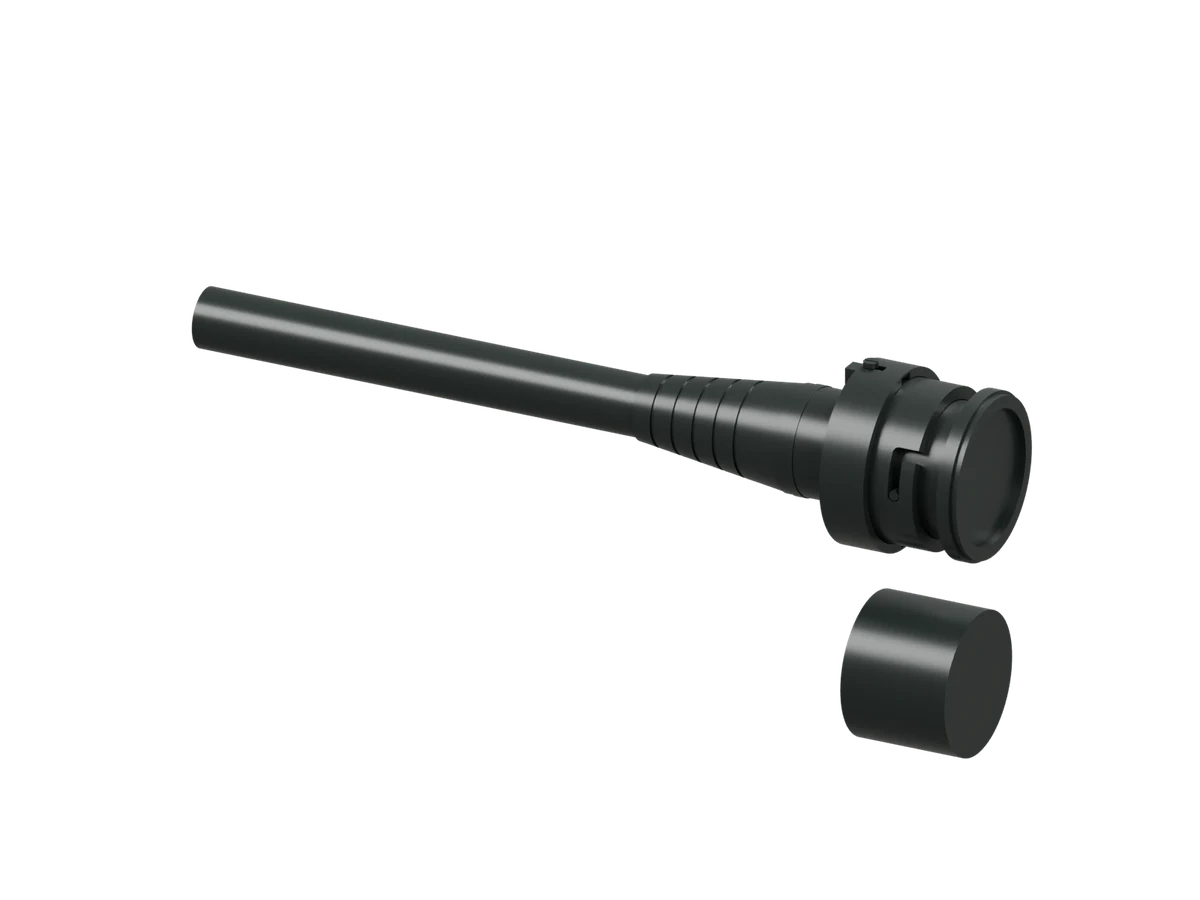
The original Subfield interface uses a graphite plug body, a 48 mm OD grip collar, a bulkhead receptacle, an orange identity band, long tapered relief and a separate protective cap. Seven contact positions correspond to the current three-large/four-signal packaging allocation; there is no released pinout.
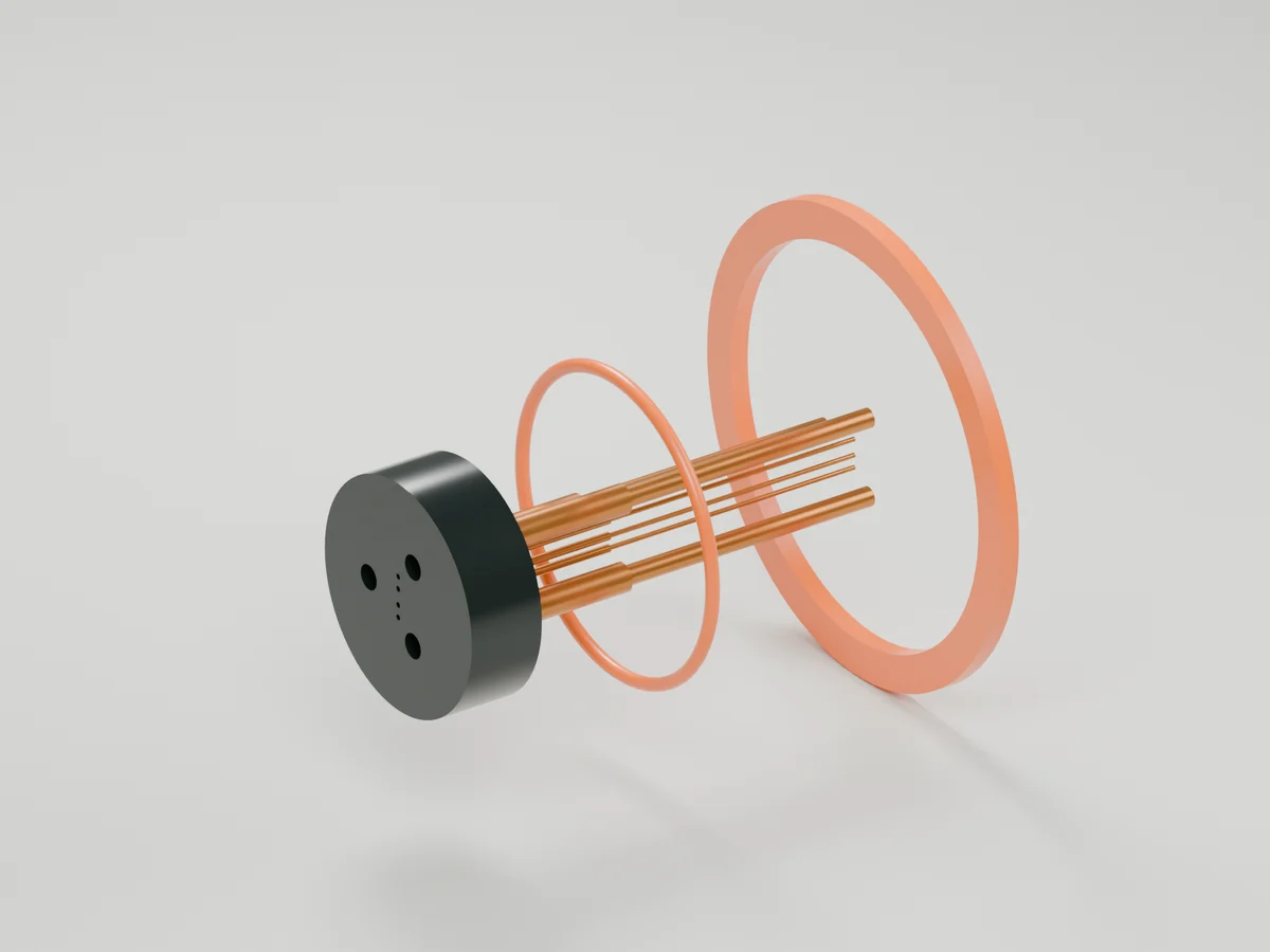
The cable-side contacts are recessed socket envelopes. The mating half includes pin envelopes and dielectric separation. Contact spring behavior, plating, termination barrels, conductor fan-out and insulation coordination still require actual contact and electrical design. A geometric recess does not establish touch-safe operation.
A fixed master key plus a second class key prevents relying on color alone. The model checks a matching 45-degree class key and mismatching 120/240/300-degree alternatives at an approach position before nominal contact engagement. This is an alignment study, not a complete abuse-proofing certification. The grip collar turns independently of the keyed plug; three studs and circumferential slots represent a bayonet coupling. Detent, preload, retention loads, wear and full tolerance/motion qualification remain open.
The cap is modeled separately alongside the connector. Cap retention/tether details and installed sealing compression require further development; it is not shown fitted at the same time as a mating connector.
Waterproofing is an assembly requirement
Four separate leak-path locations are represented: the cable entry, internal termination barrier, mating interface and bulkhead/panel seal. Fischer describes these distinct sealing regions and distinguishes mated, unmated and hermetic configurations. We must specify and test each relevant state; a catalog rating for another connector does not rate ours. Source: Fischer sealing architecture .
Longitudinal water migration is a separate concern from an intact jacket. Belden describes water-blocking constructions and the danger of moisture wicking along unsuitable cable. Subfield therefore needs qualified water blocking through the cable core and each conductor termination, including a damaged-jacket case protecting the dry enclosure. The modeled wrap and barrier volumes identify locations; they do not prove a sealed path through strand interstices. Sources: Belden waterblocking , Belden moisture ingress .
Do not mark the prototype IP68, waterproof, gas-tight, direct-burial rated or safe for energized wet mating. Define depth/time/temperature, condensation, chemistry, mated/capped/unmated states and required post-exposure electrical performance before testing. Ordinary lid access must leave the stationary Hub and managed harness undisturbed. Service remains de-energized, deliberate and keyed.
Proposed manufacturing development route
Freeze the power/data architecture and role of every core/contact. Establish electrical and mechanical loads before selecting gauge and connector inserts.
Ask a custom cable manufacturer to develop fine-strand core constructions, insulating compounds, pair lay, shield construction, water blocking and the smooth outer jacket against those requirements. This document has not been sent to a supplier.
Select actual contacts and design their crimp/termination, shield bond and tensile-member anchorage. Develop the insert, shell, coupling and gland around verified supplier data.
Develop the jacket-to-boot and barrier bonding process with compatible compounds. Test representative terminations and cable cuts before relying on a molded exterior.
Verify continuity/pin mapping, conductor resistance, insulation, signal performance, thermal behavior and fault protection on the complete intended length; then mechanical, environmental and service-state performance. Test levels remain engineering outputs.
Release controlled drawings, tooling, tolerance stacks, assembly process, inspection limits, traceability and replacement instructions only after the evidence supports them.
This revision is an original Subfield construction and product-design study. It advances the cable, connector and wire geometry; it is not a manufacturing or electrical release.
Source and revision record
Source: subfield-cable-r1/index.html
Source SHA-256: 6c6594a268dbc0af28930ed1103eb9f9da0769b8de15e80c218cd7fa148e41cf
Geometry and images describe this development revision. Current product ratings and manufacturing release require separate qualification.
Keep exploring the research.
Engineering records / Engineering record
Cable Ring Installation Audit
Geometry, analysis and remaining engineering work for Cable Ring Installation Audit.
Engineering records / Engineering record
Cable Seal Audit
Geometry, analysis and remaining engineering work for Cable Seal Audit.
Connections / Development CAD
Link threaded stops
Inspect the latest complete termination geometry with modeled threaded stops.
Return to the current product.
Explore the retrofit-only platform and its compatibility, installation and service objectives.
Explore the retrofit