Engineering records / Engineering record / CORE-TRAY-MOUNTS-R3
Core Tray Mounts R3.
Geometry, analysis and remaining engineering work for Core Tray Mounts R3.
Retained development study. Dimensions, names and checks belong to this revision—not automatically to the retrofit-only product. Manufactured tank shells are deferred. No installation instruction, certification or manufacturing release is represented.
The source reasoning
Why this detail was investigated.
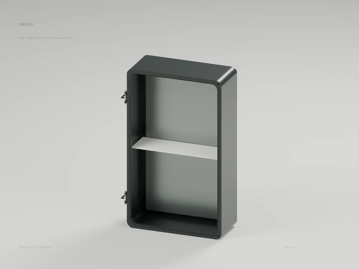
This increment adds four blind mounting bosses, four spacers and four generic M4 screw envelopes to the current exterior Core. The complete candidate contains 38 separate solids. The housing's external back wall remains intact.
Read the research and limitsResearch record
The detail behind
the study.
Source-linked work for this revision. Reported checks describe the stated model or test; physical qualification and applicability to the current retrofit remain separate.
Core tray mounting development R3
This increment adds four blind mounting bosses, four spacers and four generic M4 screw envelopes to the current exterior Core. The complete candidate contains 38 separate solids. The housing's external back wall remains intact.
Inspection render · Assembly STEP · Mount dimensions and checks · Focused test result
The inspection view omits the weather-cover assembly and faceplates to reveal the internal tray. It contains no actual electronics. The saved Blender file was reopened and its 27 visible CAD meshes were checked against source vertices; the render was visually reviewed.
Sixty-eight geometry/export checks and four focused tests passed. The complete CAD suite passed 322 tests in 1397.53 seconds for this 38-part revision. The later 62-part faceplate-support candidate has separate geometry evidence and is not covered by this test result. The previous R2 package and its 318-test result remain separate.
The four mount centers are X ±145, Y ±260 mm in the Core construction frame. Boss tops are at Z13, the 3 mm spacers support the tray at Z16, and the tray top is Z19. Screws have a nominal 10 mm under-head length. The symbolic receiver thread leaves 4 mm nominal engagement and 0.5 mm tip clearance. These are development dimensions, not qualified production tolerances or a load rating.
Faceplate, divider and rear-carrier attachments remain unfinished. Material/process selection, thread detail and capacity, tray bending, vibration, corrosion, preload, electrical packaging and physical qualification remain open. This candidate is not released for manufacture.
Source and revision record
Source: core-tray-mounts-r3/READ-ME.md
Source SHA-256: 536bc71be101b954f9a195917c0b4a3d7fb985f37a37075bb3ad881b8d5bf2ff
Geometry and images describe this development revision. Current product ratings and manufacturing release require separate qualification.
Keep exploring the research.
Engineering records / Engineering record
Core Lock Clearance R10
Geometry, analysis and remaining engineering work for Core Lock Clearance R10.
Engineering records / Engineering record
Core Carrier Formed R9
Geometry, analysis and remaining engineering work for Core Carrier Formed R9.
Engineering records / Engineering record
Core Rear Mount R8
Geometry, analysis and remaining engineering work for Core Rear Mount R8.
Return to the current product.
Explore the retrofit-only platform and its compatibility, installation and service objectives.
Explore the retrofit